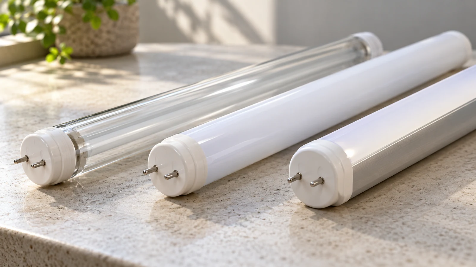
Two white LED tubes can have different construction beneath a similar finish. One may have a glass envelope with a protective coating; another may use a plastic shell; a third may divide the body between an opaque aluminum back and a PC emitting cover. Comparing only the outside color misses the parts doing the structural and optical work.
For an importer or product engineer, the material choice becomes useful when it is connected to a real requirement: which sides people see, how the source is supported, how it is handled, and what happens when it needs replacing. The best starting point is the complete construction, not a universal winner among material names.
Identify what the tube envelope is made of
Envelope, coating and internal carrier
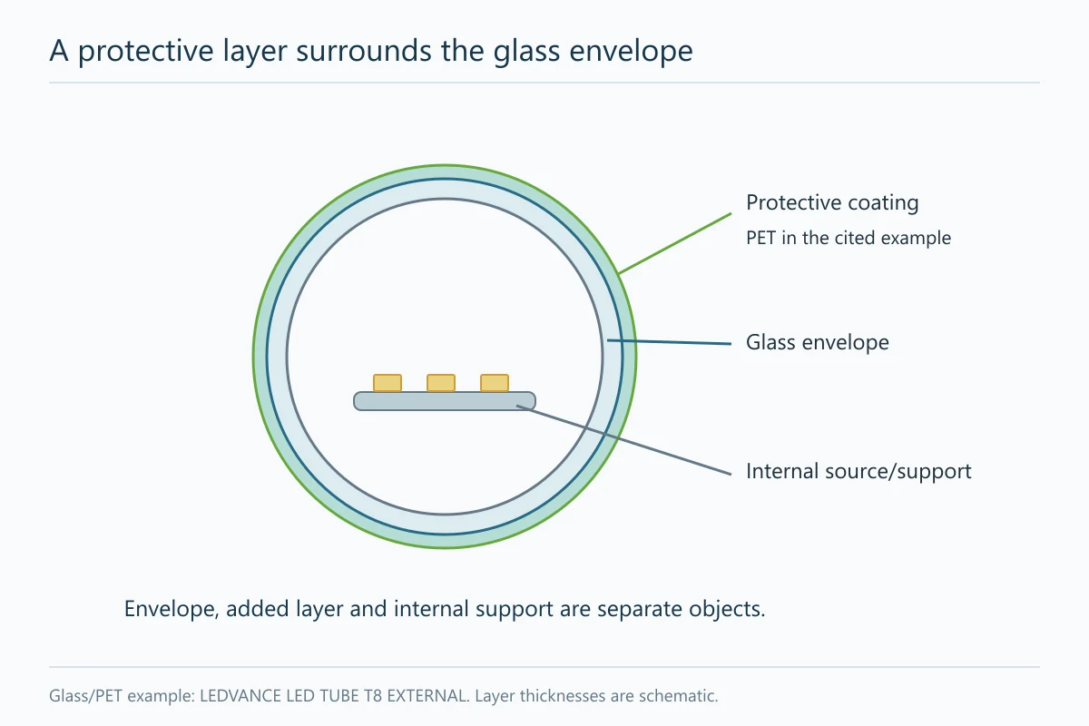
Separate three descriptions. The envelope or shell forms the main outer body. A coating or film may modify its optical or handling properties. An internal carrier supports the LED board or other components. The same material does not have to perform all three jobs.
An opal appearance describes what you see; it does not identify the underlying polymer or prove that the tube is plastic throughout. Glass can be diffusing, plastic can be clear, and an opaque rear may belong to a separate metal support. Read a material field alongside the section drawing or the actual identified part.
Also distinguish a replaceable lamp from a complete integrated linear fitting. A cover, body and end arrangement supplied as a custom assembly may have a different retention and service method from a lamp intended for existing holders. That product boundary changes what a material substitution affects.
Glass tubes can include a protective outer coating
Glass as the main envelope
A glass-envelope LED tube still uses an LED source. The glass is part of its construction and optical assembly; its presence does not make the product fluorescent. An internal LED board can produce directional light within a round envelope, depending on the board position and surrounding optical surfaces.
Current Lighting’s GEL267 R02 guide describes a particular glass-tube construction with an internal diffusing coating. It also explains a different internal optical arrangement for its signage version. These examples show why the outer material alone cannot establish the light distribution of every lamp using it.
A coating and its limited stated purpose
Glass-envelope designs can include fragment protection. LEDVANCE’s published LED TUBE T8 EXTERNAL example identifies a glass tube with a special PET coating for shatter protection. That is a product-specific construction claim, not evidence that any coated glass tube meets every site’s handling or contamination requirement.
If fragment containment matters, identify the complete product and the stated protection objective. A white surface or an unidentified film is insufficient to establish it. The relevant coating needs to remain part of the product specification, rather than disappearing under a shortened description such as “glass T8.”
Plastic shells depend on their resin and support design
Plastic is a family description
A specification that says plastic has identified a broad material family, not a precise resin grade. Signify’s published MAS LEDtube 1500mm UO 20W 840 T8 EELB record, order code 929004242202, lists its bulb material as plastic. That field alone does not identify a particular PC grade or disclose every internal support.
Where the resin matters, distinguish the named polymer, grade, surface and physical form. A property reported for one specimen or thickness cannot automatically describe a different finished tube. The material information must answer the requirement that is actually driving the choice, whether that is optical appearance, handling or an environmental condition.
The support structure beneath the shell
An outer plastic shell does not describe the entire mechanical or thermal construction. The board still needs support and a suitable heat path. A drawing may identify a carrier that the product photograph hides. Conversely, a generic sketch of a metal carrier should not be treated as proof that it exists in an unidentified plastic tube.
| Description | What it establishes | What still belongs to the actual design |
|---|---|---|
| Glass envelope | The main outer tube material | Coating, board support, ends and optical arrangement |
| Plastic envelope | A broad shell-material family | Resin grade, physical form and internal support |
| PC optical cover | The identified cover material | The separate backing, retaining interface and selected optical finish |
| Protective coating | An additional layer with a stated purpose | Its actual product scope and supported protection claim |
An aluminum-backed tube divides the mechanical and optical jobs
The metal support and rear surface
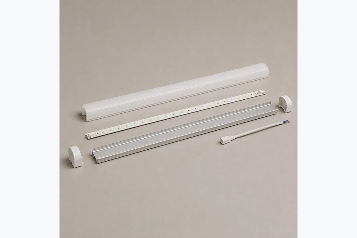
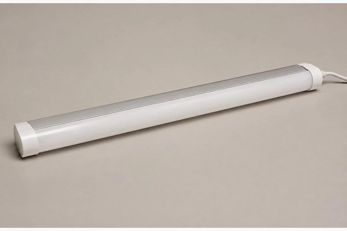
In an aluminum-backed construction, the metal portion can provide a structural area for the source and participate in spreading heat. It also creates an opaque part of the exterior. That rear can be convenient when the source faces a specific task and the backing is hidden inside the installation.
VST’s published VST-T8-600-10W and VST-T8-1200-18W platform records identify aluminum plus PC construction. They are concrete catalog examples of this material split. The entries do not provide a comparison proving that their temperatures are lower than every glass or plastic alternative.
The PC emitting cover
A backing also fixes a relationship between support and light direction. If the cap or host allows several orientations, the intended emitting face still has to point toward the task. For an exposed feature, that same orientation determines whether people see the metal rear. Treat the support, cap orientation and optical face as one geometry; choosing the material without considering that relationship can leave a structurally suitable product facing the wrong visual task.
The PC face controls the visible emitting area and helps shape the view of the LED source. Its fit to the backing matters mechanically and optically. A change in seating can expose an edge or change the distance between the source and the cover, even if the replacement appears to have the same white finish.
The custom tube-light construction page separates wraparound-diffused and directional-backed arrangements. Choose between them according to the viewed sides and useful light direction, then evaluate the selected assembly.
Trace heat from the LED board to the surrounding air
Contact interfaces and the complete path
A tube’s thermal behavior involves the LED source, board, contact interfaces, supporting structure and surroundings. Heat must move through that chain. An aluminum section cannot do all the work if the intended contact to the source is poor or the finished assembly releases heat differently from the evaluated design.
The same reasoning applies when a product has a glass or plastic envelope. Identifying that outside material does not reveal the source’s complete heat path. The carrier, interfaces and operating load still need to be understood. Avoid treating the visible shell as the only heat-management component.
The installed enclosure changes the path
A tube in open air and the same tube inside a covered or restricted fitting can experience different conditions. The host may limit air movement or place other warm components nearby. Use the selected product’s operating scope and assembled evaluation when temperature is a governing constraint.
A practical material discussion therefore asks what physical path changes when the construction changes. Replacing a backing, altering board retention or enclosing the source differently can change that path. A material-family label alone cannot calculate the resulting temperature or lifetime.
Compare the visible finish and light-emitting area
Point visibility and diffusion
For an exposed light feature, people see the unlit surface as well as the lit result. Clear, frosted and opal finishes can make the source pattern and body appear different. The relevant observation includes normal viewing distance, surrounding finishes and whether individual emitters are visible.
A more diffusing surface can help blend the source, but its output and distribution belong to that actual optical stack. A photograph taken with different exposure cannot prove that one material transmits more light. Compare identified versions and the corresponding data when a quantitative target matters.
A visible rear versus wraparound appearance
An opaque back can be unobtrusive in a concealed location yet conspicuous in a feature viewed from several sides. A broadly translucent envelope may better suit that visible form, provided its complete optical and support design serves the task.
| Construction feature | Visible consequence | Useful application question |
|---|---|---|
| Broadly translucent envelope | More of the exterior can participate in the luminous appearance | Which sides must look intentional from occupied positions? |
| Opaque backing with a defined face | The rear and emitting side have different appearances | Can the backing remain hidden while the face lights the task? |
| Diffusing surface | The view of individual sources changes | Does the selected source spacing give the intended lit face? |
| Added coating or film | The surface becomes a separate part of the material definition | Does that layer have the optical and protection role the project expects? |
Handling, cleaning and breakage affect the application choice
The handling exposure and protection objective
A protected lamp inside a luminaire and an exposed source handled during routine service face different mechanical situations. Describe the likely contact, access and protection objective. If an application requires fragment control or a particular impact performance, use evidence for the selected product rather than infer it from glass or plastic as a category.
Packaging is another part of that handling chain. Long products need support appropriate to their construction and transport conditions. A tube arriving intact does not establish how it will behave under every later impact, but suitable packing can help avoid damage before the application is evaluated. The tube packaging guide covers that separate distribution task.
The actual cleaning condition and material evidence
Identify whether the visible surface is dry-wiped, exposed to a named cleaner, or enclosed behind another cover. The cleaning agent, contact and surface finish matter. A generic assurance that a tube is durable cannot answer a specific chemical-contact question.
Keep the environmental requirement separate from appearance. A smooth white tube has not thereby established suitability for washdown, outdoor exposure or use above food. Those applications need the relevant complete-product assessment.
Choose a construction for the actual viewing and handling conditions
An exposed feature viewed from several sides
When the tube itself is the visible architectural element, begin with the intended luminous coverage and rear appearance. A wraparound-diffused construction is a sensible first direction if several viewed sides should participate in the feature. Compare the actual glass or plastic version’s appearance and support, rather than choosing solely by an assumed durability ranking.
A concealed directional task source
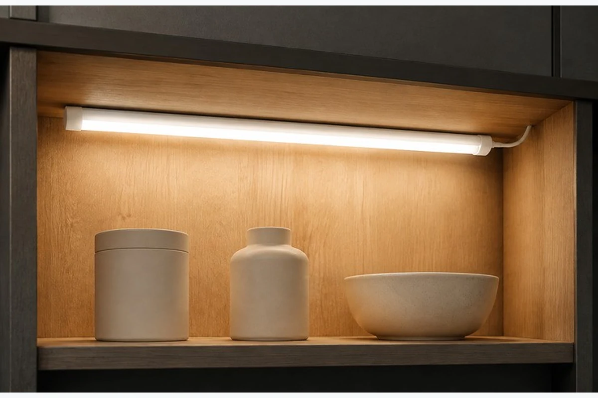
When the source sits beneath a shelf or within equipment and the rear remains hidden, a backed construction can provide a defined emitting face and supporting zone. VST’s documented aluminum-plus-PC platforms and custom assembly approach provide a basis for discussing that geometry. The selected size, load and host still determine the final build.
A protected replaceable lamp
Inside a protective fitting, the main material question may shift toward the specified lamp version and how it interacts with the host optics and handling method. A particular coated-glass product may address a stated protection objective, while another documented construction may suit the required interface. Select the complete supported lamp, not a shell material in isolation.
Keep material changes compatible with the installed system
The affected fit, light and support interfaces
A later material change can alter retention, cover seating, unlit appearance or the emitting pattern. Preserve the specific interface the host relies on, then evaluate the changed function. A white replacement surface with similar outside dimensions can still produce a different visible line.
| Change | Affected relationship | Decision to revisit |
|---|---|---|
| Different cover material or finish | Source spacing, transmission and surface appearance | The accepted optical version |
| Different backing or carrier | Board support, mounting and heat path | The complete structural/thermal arrangement |
| Different end or retention detail | Engagement and removal | The host interface and service movement |
For a new LED tube specification, describe the desired construction with its real application. That keeps the choice focused on what the material must do in the assembled product.