
A light below a stair nosing, a line in the side wall and a channel across a floor can look similar in a mood image. Their physical jobs are different. One meets the finished tread edge, another sits outside the walking surface, and the third may be exposed to direct traffic and cleaning equipment.
Choose the installation position before the profile shape. Then relate the section to the actual covering, support, light direction and replacement access. That gives you a useful way to compare products without assuming that an attractive aluminum section is suitable for every location near a stair.
Start with where the light sits relative to the walking surface
Nosing, riser and protected wall details
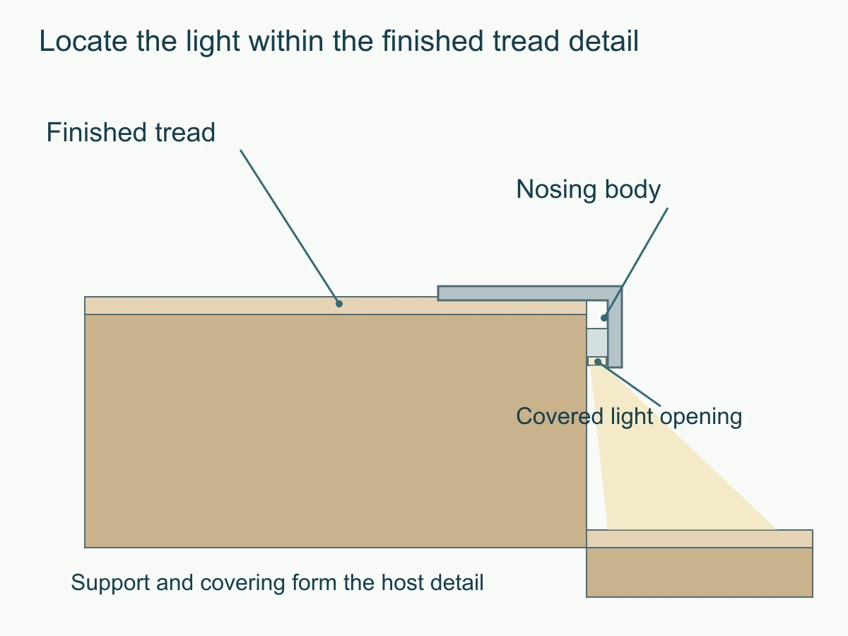
A nosing profile forms part of the front-edge detail of a tread. Its upper face, front shape and light opening have to work with the covering and riser. A riser light can occupy a vertical surface below that edge, while a wall-side light can illuminate the route from a different position.
These arrangements provide different ways to conceal the source and reach its parts. A protected wall position may keep the light assembly away from direct foot contact. A nosing places it at a construction junction that needs coordination with the tread finish.
A walking-surface channel is a different assembly
A channel that people or equipment cross needs an appropriate walking-surface construction. Its support, cover retention and exposure are different from a decorative rail fixed beside the route. A section name such as floor profile cannot substitute for evidence about the complete assembly in the intended location.
State the lighting purpose too. Decorative edge definition, wayfinding and required emergency illumination are separate briefs. An LED line selected for appearance should not be counted as a compliant emergency-lighting system without the relevant system design and approval.
The tread and floor finish define the section relationship
Finished edge, covering thickness and front projection
Use the finished tread as a reference, not only the unfinished structural surface. Tile, stone, timber, carpet and their associated layers can produce different edge relationships. Locate the upper profile face, front edge and riser relative to the completed covering.
A body may fit within the available height while presenting the wrong front projection or transition. That can affect the appearance and the way the stair detail is constructed. The complete section should therefore show which surface supports the profile and where each visible edge lands.
For a retrofit, identify which dimensions can still change. A nosing added after the covering is complete has different constraints from a detail developed before fabrication. Where the edge cannot accommodate the selected section, a protected riser or wall position may be a more suitable route.
A visible aperture with protected connections
The strip and diffuser need their own space within that detail. Locate the aperture relative to the observer, and keep the connection envelope separate from the illuminated opening. A cable turn or end fitting may require space beyond the extrusion’s listed length.
The section illustration makes those relationships visible. Fastener selection, load capacity and project acceptance require the applicable construction information rather than a generic lighting sketch.
How the three published ST sections differ
ST100 broad tread-facing footprint
VST’s LED stair profile range lists ST100 at 100 x 8.3mm, with strip space up to 15mm. Its broad upper footprint is a different geometric proposition from the deeper front forms below. Read the complete section against the finished tread and covering rather than treating its 100mm width as a luminous opening.
ST6528 rounded edge
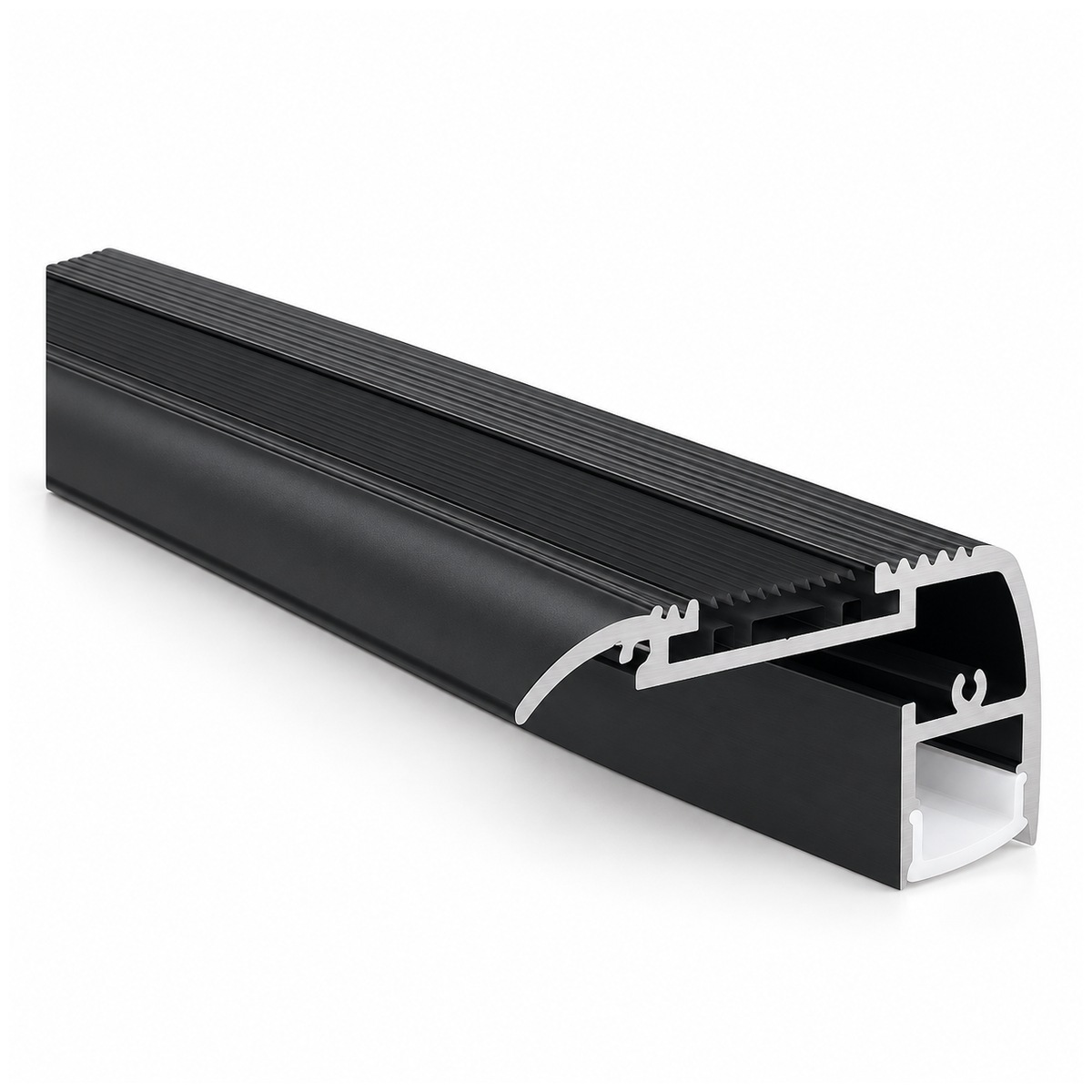
ST6528 is published at 65 x 28mm with strip space up to 13.3mm. Its upper face and lower covered aperture serve a different edge relationship. The section needs to agree with the available front depth and the intended location of the light line.
ST6935 insert construction
ST6935 is listed at 69 x 35mm with strip space up to 13.6mm and a separate upper insert arrangement. That introduces another component and interface to identify. The insert’s appearance, retention and any applicable performance information belong with the selected assembly.
For a worked section-reading decision, first mark the tread and covering on the host detail. Then compare the relevant ST upper face and front depth, locate the light opening, and identify the cover and end access. If the geometry conflicts, change the candidate or the installation position before deciding how the remaining parts will be supplied.
| Model | Published section | Published strip space | Host relationship to compare |
|---|---|---|---|
| ST100 | 100 x 8.3mm | Up to 15mm | Broad tread-facing footprint and covering edge |
| ST6528 | 65 x 28mm | Up to 13.3mm | Rounded front form and lower light opening |
| ST6935 | 69 x 35mm | Up to 13.6mm | Deeper front geometry and insert arrangement |
These catalog values screen geometry. They are not load, impact or slip-test results, and they do not define the finished stair without its support and surrounding materials.
Light direction matters on the way up and the way down
Seeing the tread edge
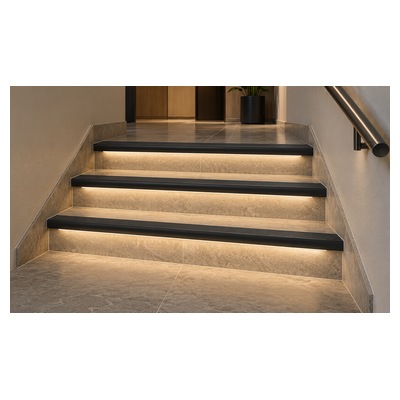
Consider the surfaces the light is meant to reveal. A source directed onto the next tread produces a different result from an exposed luminous line facing the approaching person. The position relative to the nosing and riser helps determine which surface receives light and which parts remain in shadow.
Look at both travel directions. A source concealed while descending can become directly visible from below when ascending. The selected aperture and shielding should be considered from those observer positions, not only from the camera angle used in a design image.
Direct glare, reflections and the source position
A bright visible source can compete with the edge information the design intends to provide. Changing its position, directing the opening or selecting an appropriate cover can be more useful than simply reducing or increasing power.
Reflective stone or metal introduces another view of the source. Compare the actual finish and lighting position so a reflected line is understood as part of the detail. A smooth diffuser does not by itself guarantee an unobtrusive reflection.
For a visually continuous line, the source-to-diffuser relationship matters alongside viewing direction. That optical decision should follow the selected position rather than dictate a profile that does not fit the tread.
Cover, strip and heat contact form one assembly
Diffuser retention and source fit
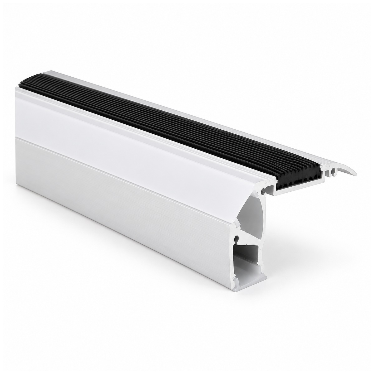
The strip-space limit is an initial width screen. The selected strip package, connector and cover still need to occupy the available cavity without interfering with the retaining features. An accessory wider or taller than the tape can become the controlling dimension.
Keep the cover code associated with the profile. A visually similar replacement may have a different retaining shape or release direction. It can also change the appearance and distribution of the emitted light.
The mounting contact and enclosing materials
The source passes heat through its attachment into the aluminum and the installed surroundings. Covering, supports and enclosed spaces influence that route. A section’s external size does not establish the permissible strip power in every finished stair detail.
Compare the source’s operating requirements with the selected mounting conditions. Where heat information is needed, evaluate the identified assembly and support rather than using the presence of aluminum as a lifetime prediction. The heat-path explanation describes why those contacts matter.
It is possible to choose a section that looks appropriate while leaving insufficient room for the connection or the intended thermal arrangement. Resolving these physical relationships together avoids discovering a new constraint after the finish is fixed.
Traffic and cleaning exposure need specific evidence
Where the load actually lands
Locate the contact surface for feet, luggage or cleaning equipment. Load can act on the aluminum face, an insert, the cover or surrounding floor material. The relevant assembly assessment depends on that location, support and retention, not only on the metal’s appearance.
If the supplied part is a profile component, identify what the completed project adds. A component photograph cannot establish the capacity of the supported finished detail. A qualified project team should resolve the applicable structural and movement-surface requirements.
Cleaning and ingress exposure
Describe the actual cleaning method and exposure. Water can reach an end, joint or cable entry differently from the front face. Cleaning chemicals can also affect the selected finish, cover or seal materials. An IP rating addresses specified ingress conditions; it is not a general material-compatibility statement.
Impact and slip information answer different questions
Impact resistance concerns a different behavior from load support or slip performance. A ribbed upper face is visible geometry, while a slip classification requires the applicable evaluated surface and conditions. Keep the evidence attached to the property it actually establishes.
| Exposure question | Relevant evidence | Why the section image is insufficient |
|---|---|---|
| Direct traffic or equipment load | Evaluated supported assembly and load conditions | The support and force position affect the result |
| Impact at the cover or edge | Applicable impact information for the selected construction | Material appearance does not define impact performance |
| Water during cleaning | Ingress scope for the complete detail and its entries | Ends, joints and connections can change protection |
| Slip on the upper surface | Applicable surface classification and use conditions | Ridges or an insert are not a test result |
Replacement access begins with the end and connection detail
How the cover and strip can be reached
Determine the cover’s release direction before the surrounding finish closes that route. A front-removable cover and an end-sliding cover impose different access needs. The end treatment should preserve the movement required by the actual selected parts.
Reaching the strip also requires access to its connection and a suitable removal route. Do not assume that because the light opening is visible, every component inside it can be changed from that face. A removable part shown loose on a bench may be trapped in the finished construction.
The service route after the finish is complete
Map access to the source, connection and separate power equipment. A serviceable driver location elsewhere does not solve an inaccessible connection at the stair edge. Equally, a removable light section does not make an enclosed power device serviceable.
This distinction affects maintenance disruption. If changing the cover or source requires disturbing adjacent stone or timber, the project has a finish-repair task as well as a lighting task. The useful design response is to preserve the necessary access while selecting the detail, rather than adding a generic promise of easy maintenance.
Actual electrical service follows the selected equipment instructions and qualified-person procedures. The access discussion identifies the physical route; it does not provide a connection method.
Selecting and scheduling the finished detail
Choose the section around the actual tread
Return to the finished-tread drawing with the candidate’s section, covering relationship and light aperture identified. A broad ST100 footprint, rounded ST6528 edge and deeper ST6935 insert form are different routes to compare. Prefer the route that fits the actual host and intended view, then resolve the required assembly evidence and access.
Keep mixed lengths and supplied parts identifiable
Projects with different tread widths need a part schedule that distinguishes lengths and end treatments. The aluminum length, illuminated length and supplied end parts may not be identical quantities. Keep those fields separate so an order can be compared without assuming which accessories are included.
| Schedule item | What to identify | Reason |
|---|---|---|
| Stair or floor position | The actual location and finished-detail revision | Connect the part to its intended construction |
| Section | Model, cover and insert where applicable | Keep different edge and retention forms separate |
| Length and end treatment | Cut length, end parts and connection allowance | Avoid treating the body alone as the complete installed length |
| Supplied scope | Profile parts, lighting parts and remaining host work | Compare offers and plan assembly accurately |
The result should be a defined construction relationship, not just a selected extrusion. That gives the project team a clearer basis for sourcing, assembling and later replacing the lighting while leaving the required project approvals with the responsible specialists.