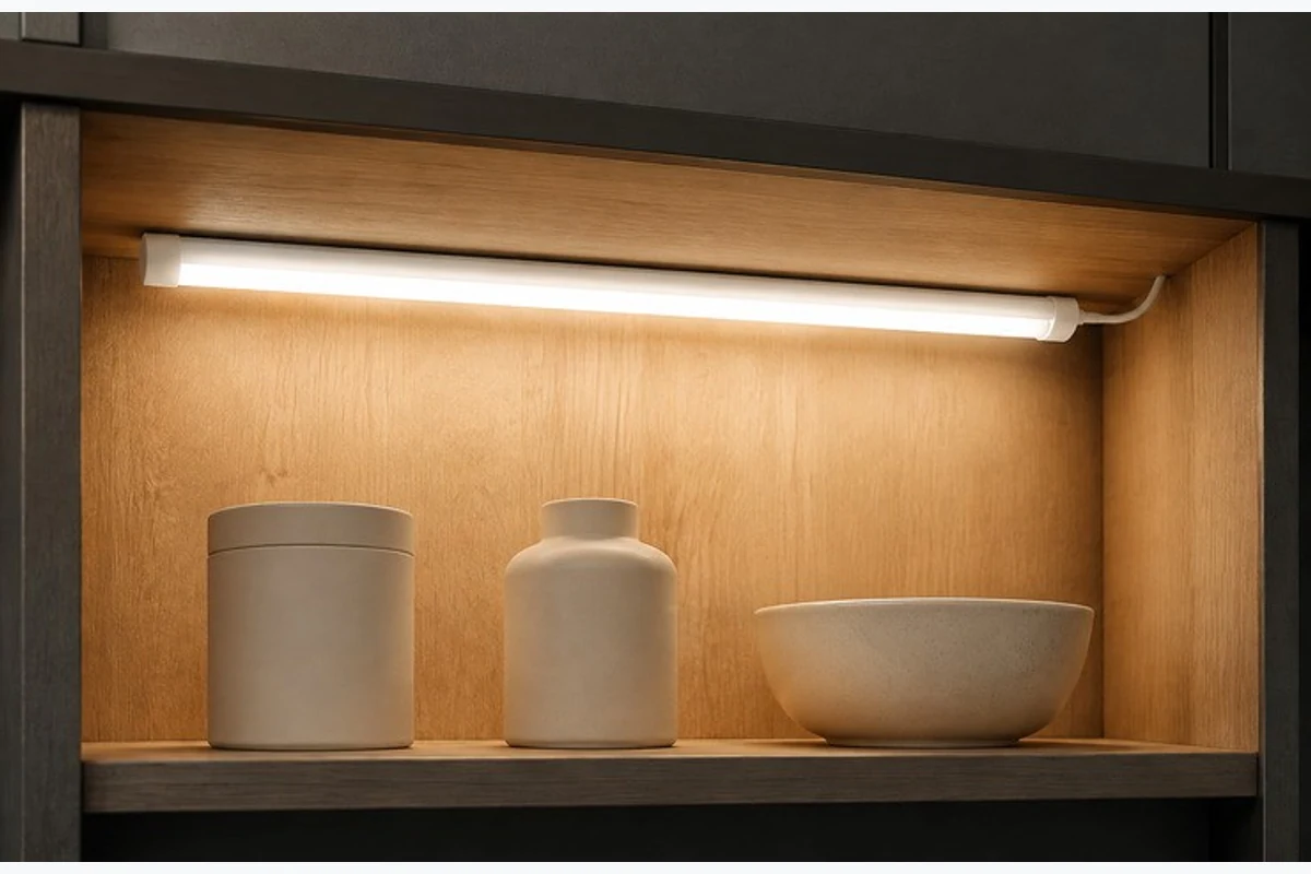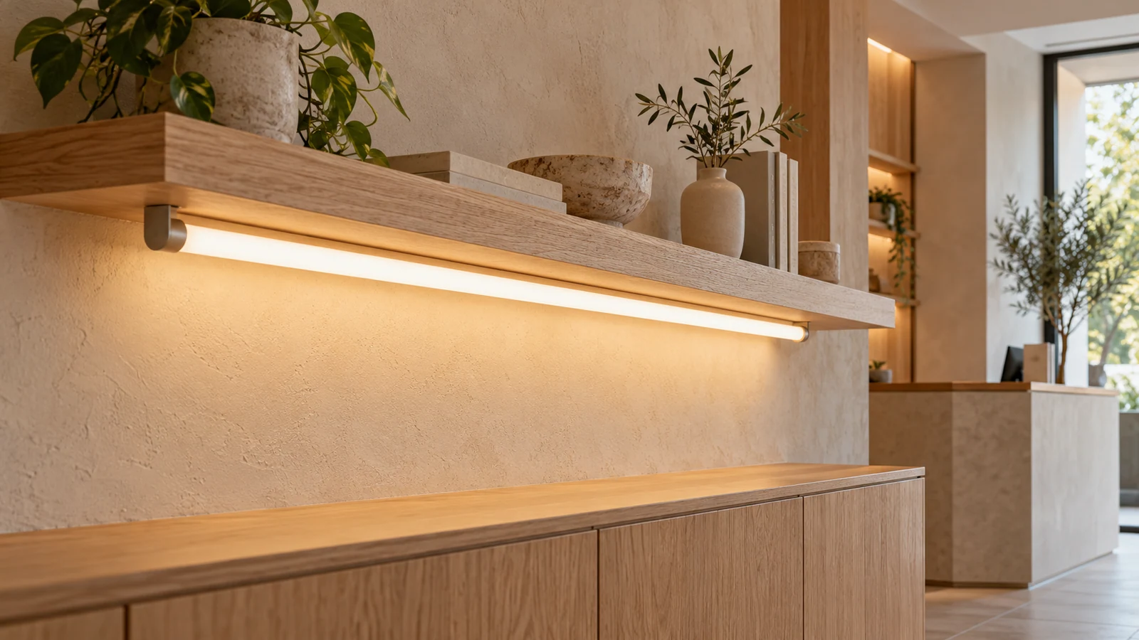
A tubular source at the front of a shelf can be part of the architecture; the same outline hidden behind a lip can simply light the objects below it. Those two locations ask different things of the diffuser, opaque backing, end hardware and mounting detail.
For an architectural specifier or OEM fixture designer, the first choice is what people should see. Develop the source around that viewing requirement, then coordinate its physical envelope with the joinery or other host. A familiar tube shape does not settle whether you need a replaceable lamp, a custom module or a complete luminaire.
Where the tube belongs in the architectural detail
A replaceable lamp, a tubular module or a complete luminaire
A lamp-style replacement belongs to an identified holder and operating arrangement. A custom tubular module is developed around a host interface. A complete luminaire includes the product’s intended mounting and electrical system. Buying one object while drawing space for another can change both the installation and later service.
This distinction matters when looking at architectural tube-lighting references. Some show cylindrical wall lights or suspended luminaires rather than a light source that another product incorporates. Their finished appearance may be useful inspiration, but their mounting, output and controls cannot be transferred to an unrelated tubular assembly.
VST’s custom tube-light page distinguishes wraparound-diffused and directional-backed construction. Coordinate the selected source geometry with the interior detail so that the finished assembly has the intended viewed surfaces and service access.
Visible features need light around the viewed sides
Multiple sightlines and the opaque rear
If the tube itself is the intended feature, draw the sides occupants will see. A source beneath a shallow ledge may be visible from the front and below. A freestanding display could reveal its rear as someone walks around it. An opaque backing that disappears from one viewpoint may become prominent from another.
A wraparound-diffused construction is a useful starting direction when several viewed sides should form the luminous feature. Its actual internal source and support still determine which portions emit and how the surface looks. A round cross-section alone is insufficient to promise equal light in every direction.
Diffusion, point visibility and the unlit surface
The feature is also visible in daylight or when switched off. Consider the diffuser’s unlit color, surface texture, end finish and relationship to nearby wood or metal. A line that looks smooth in a distant rendering can reveal individual LED points or a conspicuous dark end at normal viewing distance.
Source spacing and diffuser geometry should solve that appearance together. More output can make an unwanted point pattern more obvious. Where the design depends on a smooth luminous face, evaluate the chosen source and cover from the actual occupied positions, not only directly in front of an isolated sample.
Concealed task lighting benefits from a defined emitting face
The target surface and source orientation
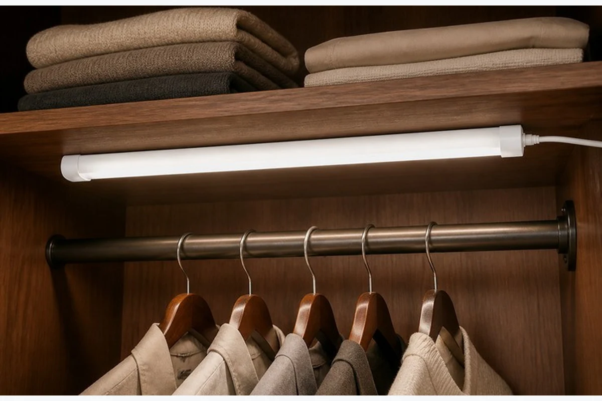
A concealed tube has a different purpose: put useful light on a shelf face, display object or work surface while keeping the source itself secondary. A directional-backed construction can provide an emitting face aimed toward that task and a rear area for support.
Locate the receiving surface in section. A source close to a shelf’s front edge can interact differently with the shelf lip, objects and viewer than one near the back. The useful choice depends on what must be illuminated and which obstructions lie between source and target. There is no universal offset that solves every detail.
Shielding the source at the normal viewing position
A concealing lip can reduce direct source visibility, but it can also obstruct useful light. Draw both the eye line and the path toward the task. If hiding the source blocks the required area, change its position or the host detail before choosing more wattage.
| Requirement | Visible luminous feature | Concealed task source |
|---|---|---|
| What should be prominent? | The tube’s luminous surface and finished ends | The illuminated object or receiving surface |
| Useful construction direction | Diffusion across the intended viewed sides | A defined emitting face with a hidden backing |
| Primary geometric check | Viewed sides, dark ends and mounting visibility | Source-to-task path and normal sightline |
| Condition that changes the choice | An opaque rear becomes visible | The concealing detail blocks useful light |
Lit spans, dark ends and joints shape the visual rhythm
Active light versus overall length
The overall assembly length includes parts that may not emit light. End caps, connections and retaining features occupy space. A drawing should identify the active span separately from the outside envelope, especially when the tube is a visible line.
A dimensional request that says only “1200mm light” leaves that distinction open. It could mean a product fitting inside a 1200mm boundary, a nominal size family, or a required 1200mm illuminated span. Those meanings can lead to different assemblies.
Repeat spacing and the end hardware
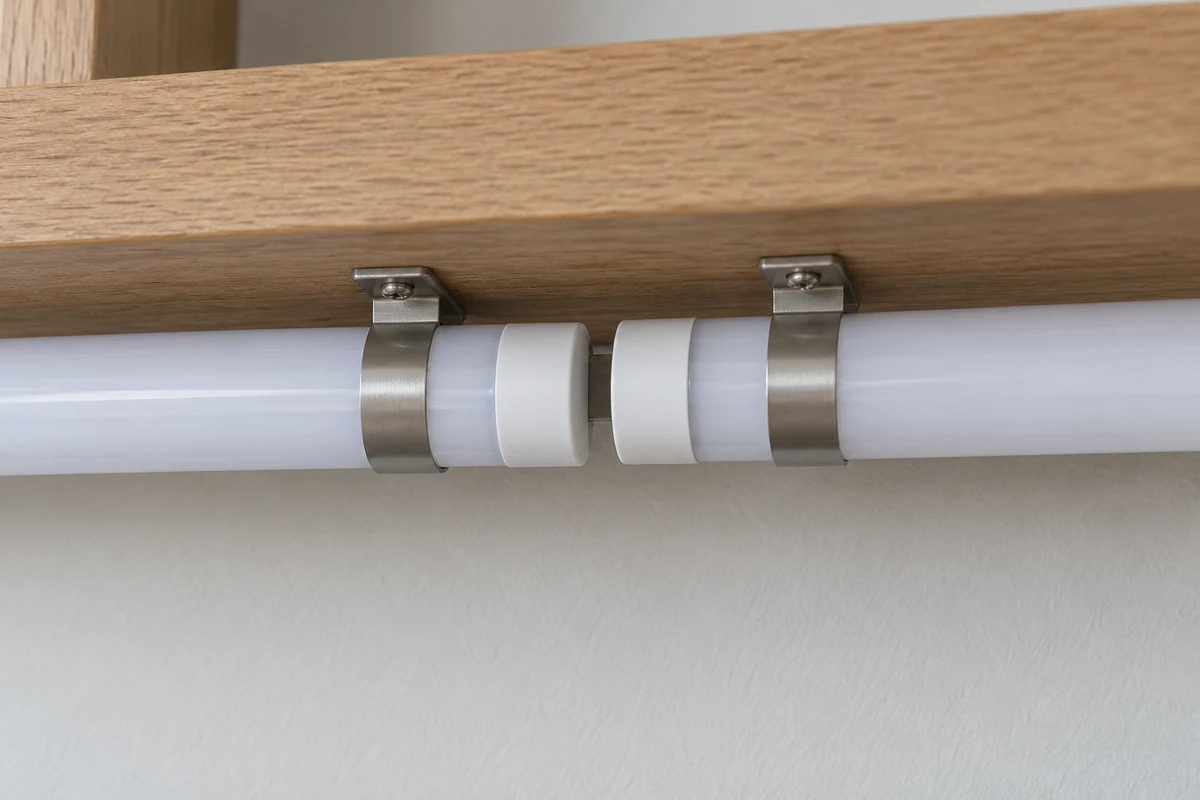
When sections repeat, the visual rhythm includes their ends and joints. Bringing two bodies together does not necessarily bring their emitting areas together. A connection allowance or mounting feature can create a visible dark interval.
Decide whether those intervals should be concealed, aligned with a joinery division or deliberately expressed as part of the feature. A regular joint aligned with the host can be more intentional than an irregular attempt to imitate an uninterrupted line. A seamless appearance needs evidence from the actual optical and mechanical design; it cannot be assumed from end-to-end contact.
Read a repeated joint from one active span to the next. The interval can include the first section’s non-emitting end, the physical spacing and the second section’s non-emitting end. Measuring only the visible gap between bodies misses the two end zones. This matters when a designer coordinates several sources with cabinet divisions: the luminous rhythm and the outside product rhythm may be different lengths.
The mounting detail changes what occupants can see
Clips, orientation and sightline
A clip can retain the tube while also becoming part of the visible object. Its position may interrupt the luminous surface, expose an opaque portion or constrain rotation. Locate the retention in the same section that shows the viewer and task.
For a concealed directional source, the support may sit behind the emitting face. For a visible feature, the fixing should preserve the intended surface appearance from the relevant sides. A small support is not automatically discreet if it falls in the brightest part of the line.
Retention and a reachable release
Clean appearance and later removal need to coexist. A hidden fixing can work when its release or extraction route remains accessible. If a permanent panel traps the lamp or module, routine replacement may become a joinery task.
Define the retention concept and service movement at the planning stage. Actual load-bearing hardware, fixing details and installation acceptance belong to the appropriate product and project design, not a generic lighting article.
Driver position and replacement movement consume real space
The electrical assembly within the spatial envelope
The chosen source arrangement determines where the regulating electronics and connections belong. Some functions may sit inside the tube; others may require separate equipment. Do not reserve an arbitrary external driver box when the selected system has a different architecture, or omit one that the actual product requires.
Reserve space and access for the selected system’s actual arrangement. A shallow feature can have enough room for its luminous body while leaving no suitable location for the intended end connection or serviceable equipment.
Removal direction and reachable connections
Show how the service object leaves the host. It may need axial travel, a front release or access through a removable panel. The correct movement depends on the intended assembly. A tube that fits the final opening can still be difficult to install or remove if neighboring parts block that path.
| Object or movement | Spatial question | Effect on the design |
|---|---|---|
| Tube and end hardware | Which boundaries contain the complete product? | Sets the available envelope before defining the active span |
| Support and retention | Where is the product held and released? | Changes visible interruptions and access |
| Required operating equipment | Where does the selected system place it? | Creates a real equipment and service-space requirement |
| Extraction movement | What has to move, and in which direction? | May require a removable host detail |
Color and surface appearance belong in the room context
Adjacent finishes and the selected white
A visible tube is judged beside the materials around it. White appearance and the rendering of wood, merchandise or painted surfaces should follow the room’s design brief. An isolated catalog image cannot establish that relationship.
Use the selected optical and color version in the intended host context. The tube size, output and CCT guide explains those separate parameters; they should support the architectural choice rather than replace it.
The visual consequence of later replacements
Separate an unlit finish reference from the lit appearance. A diffuser can sit comfortably beside a painted surface in daylight yet look different when the source operates. Conversely, two sources with a matching color label can reveal different point patterns because their spacing and covers differ. Evaluate the combination from the positions the room will use, keeping camera exposure consistent if photographs are used for comparison.
Later units may be installed beside surfaces and diffusers that have aged. Keeping the original part identity is useful, but the visible result also depends on the installed context. Where adjacent sections form one feature, define what appearance must remain consistent and which parts are replaceable together.
A complete feature-line layout from fixed dimensions
Calculate the available active-span allocation
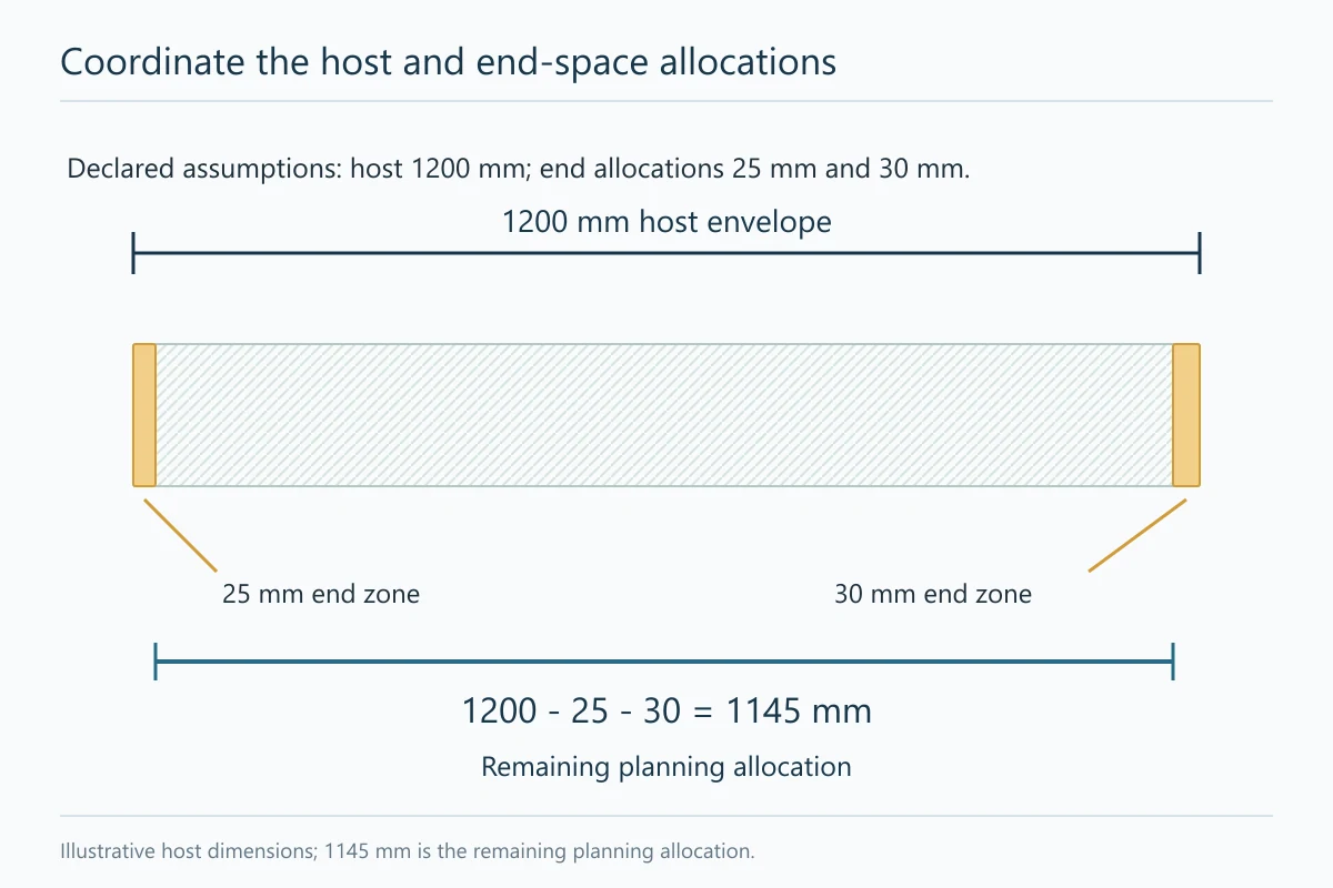
Take an explicitly assumed interior detail with a 1200mm clear host envelope. Reserve 25mm at one end and 30mm at the other for the end and connection zones. Subtracting those allocations leaves 1200 – 25 – 30 = 1145mm for the remaining span.
The 1145mm result is an upper planning allocation. It is not a VST stock length or a promise that every millimeter within it will emit light. The actual caps, support, optical end effects and any other retained features still determine the developed active span.
Choose the arrangement and record its spatial limit
Suppose this same declared detail is visible from the front and below, and its purpose is to appear as a luminous element. Start with a diffused construction that serves those viewed sides. If instead the requirement changes to lighting objects behind a concealing lip, a backed directional arrangement becomes the more appropriate starting direction.
The input dimensions, calculation and viewing task now produce a usable result: a source-envelope limit and a preferred construction direction. The host drawing can carry that constraint into development. It does not yet specify a circuit, approved fixing or measured illuminance.
If a proposed standard assembly consumes more of the end space than the detail allows, change the host, select another assembly or develop the affected end interface. Increasing output will not recover length occupied by hardware. This is a fit problem with a geometric response.
Standard components and custom parts have different jobs
An existing assembly that fits
If an existing tubular assembly meets the viewed-side requirement, physical envelope and service method, deeper customization may add little. Keep its supported construction rather than redesigning every part merely because the project is architectural.
A changed carrier, end or diffuser interface
Customization becomes useful when a specific constraint cannot be resolved by that existing assembly. A different end interface, active span or visible face can require a focused change. A new carrier or profile can involve a broader development scope.
| Unmet requirement | Useful direction | Relationship to resolve |
|---|---|---|
| Standard assembly fits and looks appropriate | Evaluate the existing configuration | The actual host and source version |
| End hardware conflicts with the detail | Review the end or connection arrangement | Envelope, retention and extraction |
| Required viewed sides differ | Review cover and backing geometry | Source position, diffusion and visible support |
| Available structure cannot support the required span | Review carrier or host design | Mechanical support and the resulting light-source assembly |
A coordinated brief connects the light source to its host
The host detail, visual task and source boundary
The useful output is a coordinated detail: what should emit, which sides are viewed, where the complete product fits and how its service object is reached. Keep the remaining source and host decisions connected to those requirements.
| Drawing or brief item | Decision it connects | Reason to include it |
|---|---|---|
| Viewed sides and receiving surface | Visible feature or concealed task source | Keeps the optical choice tied to the intended use |
| Envelope and active-span allocation | Host boundaries and end treatment | Prevents nominal length from hiding occupied space |
| Retention and service path | Installed appearance and replacement movement | Preserves access after surrounding work is complete |
For a wider strip-and-profile system, use the separate architectural linear-lighting guide. A tubular-source brief can stay focused on its own emitting surface, end treatment and host interface.