
An existing cabinet supply can settle the voltage question before you compare a single reel. If the host requires a particular regulated input, the strip and controls must work within that interface. For a new installation, you have more freedom: compare current, the actual powered sections and the lengths that fit the furniture, then choose the matched system.
The useful comparison is between two identified strip arrangements serving the same lighting task. A voltage label alone leaves the source output, cut unit, connections and operating conditions open.
The input that fixes your first choice
An existing host supply
Keep an identified 12V strip on its specified input when replacing part of an existing system. Changing to 24V involves selecting a different strip circuit and checking the supply and controls that serve it. A connector that mates mechanically can still join electrically incompatible parts.
Read the host output specification, including its type and supported operating range. This is particularly important when someone describes the source only as a 12V battery. Charging conditions and transients are additional supply questions; a nominal battery label cannot establish that an ordinary indoor tape is suitable for direct connection.
A new matched strip system
Where neither voltage is fixed, start with the light function and the physical sections. A long light line, many short furniture inserts and an existing dimmer can lead to different choices. Select a strip, supply and controller that form a supported arrangement, rather than choosing the reel first and adapting everything else around it.
For a new arrangement with a substantial distribution load, 24V is often worth investigating first because the nominal current is lower at the same power. A precise short-section requirement can make another source platform more useful.
What changes at the same nominal load
Current from watts and volts
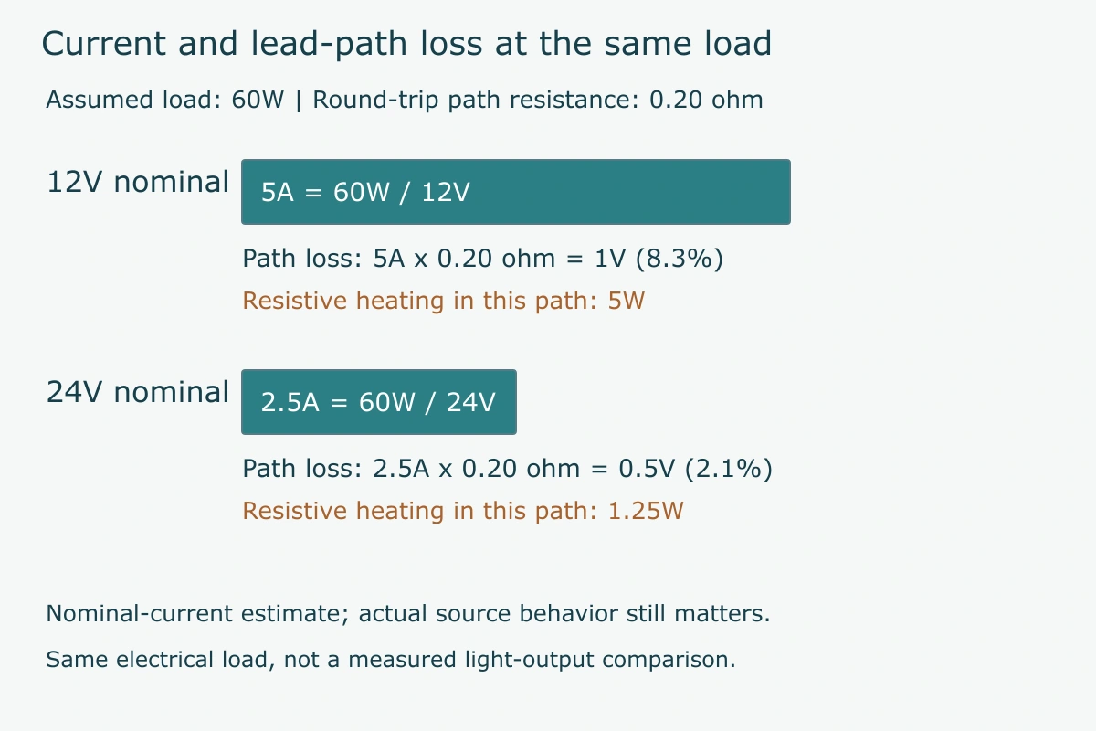
Use I = P / V, where current I is in amperes, power P in watts and voltage V in volts. Assume two candidate strip systems each have a nominal 60W load at their respective rated inputs. The 12V candidate draws 60 / 12 = 5A; the 24V candidate draws 60 / 24 = 2.5A. The comparison concerns equal electrical loads, not proof that the two sources produce equal light.
The lower current matters along the path carrying the combined load. Its connector and conductor still need to support the actual conditions, but the starting current budget is different. Doubling the supply voltage for the same nominal wattage halves that nominal current.
A cable-path estimate with declared assumptions
For this teaching calculation, also assume a round-trip lead-path resistance of 0.20 ohm. Using voltage loss = I x R gives 1.0V for the 5A path and 0.5V for the 2.5A path. Relative to the rated voltages, those estimates are approximately 8.3% and 2.1% respectively.
This makes the 24V route the better starting direction for the stated equal-load, equal-resistance comparison. It does not establish a permitted cable length or an acceptable loss threshold. The calculation holds current at its nominal value; the actual strip current can change as its input voltage falls. Final design uses the selected source behavior, real route and applicable evaluation method.
Read powered-run limits as model data
Reel length
A reel describes how material is supplied. VST’s C320W1008 page lists a 5m roll, but that shipping field does not specify every permitted feed arrangement. Keep packaging length separate from the electrical section you intend to power.
The permitted powered section
Look for the maximum section or feed arrangement for the exact model, operating mode and source input. Strip copper, power density and the circuit architecture affect the current traveling through the tape. Two 24V products can consequently have different run limits.
The separate supply-lead route
The cable between the supply and tape also has resistance. An appropriately divided strip arrangement can still have a poor lead path. The LED strip voltage-drop explanation develops that distinction and the information needed for a loss comparison.
| Field | What it describes | Use in the decision |
|---|---|---|
| Reel length | Material supplied in one roll | Plan quantities and preparation |
| Powered section or feed limit | The model’s supported electrical arrangement | Define the actual source sections |
| Lead route and resistance | The path from equipment to the section | Evaluate loss before the tape input |
Cut intervals can change the practical winner
Whole circuit units
The smallest prepared length follows the selected circuit’s cutting arrangement. C320W1008’s published unit is 50mm. S2835L144W0608, also a 24V source, lists 62.5mm. Those two units produce different available lengths even though the voltage is the same.
If a furniture opening demands an exact active length, calculate the whole units that fit after allowing for the completed ends. The next longer unit may be too large, while the next shorter one may leave an unwanted dark space. That is a source-platform and host-detail decision.
The chosen voltage variant and its drawing
C384W1005’s public record lists 12V/24V variants and a 41.66mm cutting field. A shared table is a useful starting reference; its rounded value is not a manufacturing tolerance or a substitute for the chosen variant drawing. Compare the actual cutting record when preparing an order.
A 12V design may offer a helpful short unit, but the label does not guarantee it. Read the model fields and the end geometry together. A physically better fit can justify retaining the existing voltage or choosing a different platform.
For another dimensional illustration, assume 312.5mm of active space remains after the real ends have been allowed for. Five of the published 62.5mm units occupy that space exactly, while six 50mm units occupy 300mm. If the task needs the whole active line filled, the former is the better nominal length candidate. Its SMD appearance and other fields still need to suit the task. Both examples use 24V, so the actual circuit unit decides this fit comparison.
Compare light output and heat on equivalent terms
Source construction and output conditions
Compare the light function before deciding that two reels are alternatives. A fixed-white COB source, tunable-white SMD tape and an addressable color source require different output and control fields. Their input voltage does not make them equivalent products.
Use W/m, the relevant light-output field, white or color option and operating condition from each identified source. Then consider the cover, host and target surface. Equal nominal watts do not establish equal delivered illumination; a product-level lumen figure also leaves the final spatial distribution unresolved.
For example, VST publishes 10W/m for C320W1008 and 6W/m for S2835L144W0608. Choosing between them requires the optical task as well as the input budget. The lower-wattage option is useful only if its supported assembly supplies the required light.
Where lower path current changes heating
Resistive heating in a defined path follows I squared x R. In the earlier assumed 0.20-ohm path, 5A gives 5W and 2.5A gives 1.25W. This explains a benefit of reducing current through that path.
The source board has its own heat generation and mounting relationship. Tape power, internal current control, contact with its carrier and the surrounding environment remain relevant. Lower lead-path loss should not be turned into a universal statement that every 24V strip runs cooler or lasts longer than every 12V strip.
Also keep the current boundary clear. The lead may carry the combined load of several source sections, while the current through an individual LED string follows that source’s internal circuit. A measurement or rating at one boundary cannot be relabeled as the other. This is why the strip model and feed arrangement matter after the simple voltage calculation.
How layout changes the voltage decision
Many short prepared sections
A wardrobe or display fixture may contain many small sections with individual end spaces. Here, usable cut lengths, connection envelopes and a fixed host input can outweigh the convenience of a higher-voltage distribution arrangement.
Choose the source platform that satisfies those physical sections and the actual task. If a change from 12V to 24V would require replacing an otherwise suitable supply and controls, include that work in the comparison. A cheaper reel can be a poor overall substitute.
A longer distributed light line
For a new longer line, investigate a matched 24V route and its documented section/feed limits. Its lower nominal current can help the lead-path budget, as the worked comparison showed. Resolve the actual section arrangement before assuming one continuous powered run.
| Constraint that leads the choice | Direction to investigate | What could change it |
|---|---|---|
| Identified fixed 12V host | A supported matching 12V assembly | An approved redesign of the complete input and controls |
| Very specific short active lengths | The platform with useful whole cut units | End allowances or the host opening change |
| New longer distributed load | A matched 24V route with documented feeds | Source performance or a fixed interface requires another arrangement |

Keep controls and replacements on the same variant
The supply and controller output
Read the actual output range and current capacity of the selected equipment. A controller capable of operating at several input voltages does not necessarily convert one voltage into another. Its supported circuit and instructions determine the relationship.
Do not connect a specified 12V strip to a 24V output. Supply replacement involving mains belongs to qualified electrical personnel following the applicable instructions and local requirements. For the product-selection stage, identify the exact input and control variant before considering a replacement.
A spare section that matches the installed circuit
Retain the source identity, voltage, light option and prepared-end version when ordering spare sections. An apparently identical reel can have a different circuit or white appearance. Matching the connector shell alone leaves those differences unchecked.
For repeated furniture assemblies, labeling the prepared variant gives purchasing and assembly teams a specific reference. The consequence is practical: the replacement should fit the host and perform the intended function without reopening unrelated parts of the design.
A partial replacement deserves particular care where older sections remain visible. Matching voltage resolves the input question, but the new source’s CCT option, rendering and cover can still change the appearance beside the retained light. Compare those actual options rather than treating the voltage as the complete replacement specification.
Make the choice from the constraints you actually have
When 12V remains the practical route
Retain a supported 12V route when the identified host requires it or the appropriate source platform best serves the short sections. Judge the complete arrangement, including any regulation and control requirements.
When to develop a 24V option first
For a new equal-load design with meaningful distribution resistance, start by evaluating 24V. Keep the actual cutting, light output and permitted powered sections beside that electrical advantage.
| Your starting condition | First decision |
|---|---|
| A working system with one section to replace | Match the identified installed variant |
| A tight host opening with no fixed supply | Find a source and finished-end geometry that fit |
| A new distributed load | Compare nominal current and actual path/section constraints |
VST’s 24V strip configurations provide model-level starting points. The useful result is an identified source, input and section arrangement that serves the job, with the remaining host conditions clear.