A tube can run normally at full output and still be a poor choice for a presentation room. Reduced light, low-level startup and the response of several lamps together depend on the electronics and the control equipment working as a combination.
If you are replacing lamps while keeping the room controls, begin with the control method and equipment reference. If the controls can change, define the required scenes first. Either route gives you a more useful starting point than a catalog entry that says only dimmable.
What makes an LED tube dimmable?
The lamp electronics
LED light output is regulated by its driving electronics. A dimmable lamp system provides a supported way for a control command to change that output. Depending on the product, the relevant electronics may be inside the tube, in compatible control gear or in a separate LED driver.
The important purchasing question is which combination performs the required behavior. A controller and lamp can each be described as dimmable yet use different methods. The selected electronic version must receive and respond to the intended command.
Dimming, switching and color selection
A sensor may switch a circuit on and off, change between preset levels or operate a compatible dimming system. Read its stated function rather than treating sensor as another word for dimmable. Similarly, selecting a color temperature changes white appearance; it does not necessarily provide brightness adjustment.
Describe the room behavior plainly. For example, a presentation scene might need lower desk-area light while limiting light on the screen. An occupied corridor may require only scheduled or presence-based switching. These are different briefs, even when they use similar lamps.
Follow the control path through the system
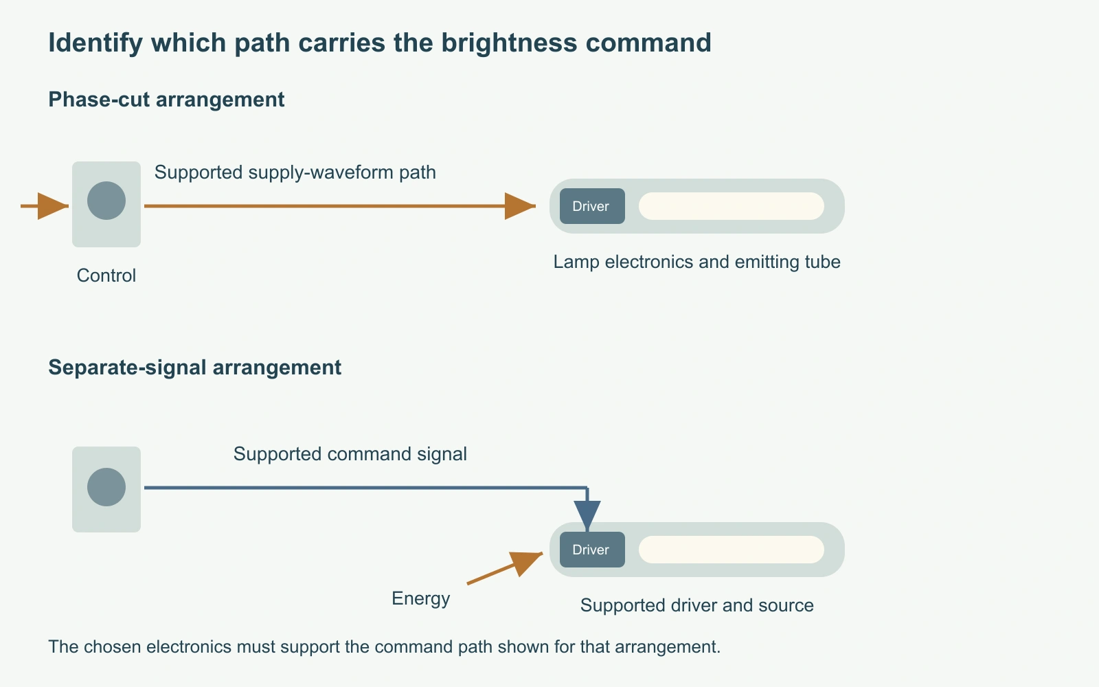
A phase-cut supply path
In a phase-cut arrangement, the control changes the supplied waveform and compatible lamp electronics interpret that change. The electronics must be intended for the relevant control method and equipment. A generic household LED dimmer is not automatically suitable for every tube carrying a dimmable label.
For an existing installation, identify the control reference before choosing a replacement driver version. The physical lamp size does not reveal how its electronics respond. Two outwardly similar tubes can therefore require different controls.
A separate control signal or supported network
Other arrangements communicate the brightness request through a separate control path. A suitable 0-10V driver responds to its specified control signal, while a supported digital or networked system uses the intended interface and equipment. The power path and the command path have different jobs.
Manufacturer-specific wireless tube systems also exist. Their presence does not establish that an unrelated lamp supports the same network, application or gateway. Decide which control path the room will use, then match the equipment within that path. Any electrical work requires the selected system instructions and a qualified professional; a functional relationship diagram is not a connection drawing.
A dimmable label does not identify the complete pairing
Version and interface
VST’s published T8 records include control-option labels such as TRIAC, 0-10V and DALI. These identify configurations to discuss. They do not show that one delivered driver can change freely between all those methods, or that a specific installed controller has been tested with the lamp.
| Method | Relevant command path | Equipment information that changes the choice |
|---|---|---|
| TRIAC / phase-cut | Supported waveform control through the supply path | Control reference, intended electronic version and connected quantity |
| 0-10V | Supported separate control-signal path | Driver/control references, operating range and off behavior |
| DALI | Supported digital control interface | Exact driver version and applicable system documentation |
Published options versus a supported combination
For a concrete example, the published VST-T8-600-10W platform record includes a non-dimmable label alongside TRIAC, 0-10V, DALI and sensor options. The record describes a platform range, not the driver identity of a sample delivered to a project. A useful order line therefore distinguishes the selected electronics from the 600mm body and 10W power description. Otherwise, a later buyer can repeat the dimensions while unintentionally changing the control behavior.
The dimmable LED tube product page should be read alongside the selected lamp and driver information. Its size range helps with the mechanical shortlist; the accepted control version belongs in the electrical specification. A protocol label alone cannot establish certification, all-device interoperability or the useful low-output range.
The lowest useful level is a room requirement
Control position and useful light output
The position of a slider, the electrical command and the light you perceive are different quantities. Halfway along a control does not necessarily mean half the lamp’s rated output or half the apparent brightness in the room. State the required result in terms of the task the occupants need to perform.
A low-output claim should also identify its basis. Useful questions include whether the figure refers to light output, what equipment produced it and whether the lamp can start at that setting. Without that context, two advertised percentages may describe different things.
Presentations, daylight and ordinary work
For presentations, people may need to read notes while the screen remains legible. At window-side desks, the desired artificial light can change with daylight. A service room may simply need reliable full output when occupied. There is little value in paying for a deep-dimming capability that the space never uses, while a room depending on low output needs more than a smooth full-brightness demonstration.

Startup, transitions and off behavior need separate descriptions
Starting from a low setting
A lamp that dims down after starting may behave differently when power is applied with the control already low. Distinguish these operating situations in the brief. The relevant product and combination information should describe the behavior expected during ordinary use, rather than only the lowest level reached after the lamp is running.
Transitions matter too. A room user may notice an abrupt change between nearby settings, a delayed response or a difference between lamps. These observations help define the operating requirement; they should not be presented as a diagnosis of a component without evidence.
Switch-off and power restoration
For users, the distinction can be simple: the room should begin in the intended scene, respond predictably to the control and reach the intended off state. Translate those expectations into the equipment brief without promising a numerical low end that has not been documented. This helps the project compare usable behavior rather than merely count which products advertise the longest dimming range.
Clarify whether the intended off action removes power, sends a control command or leaves another part of the system active. That distinction belongs to the selected equipment. A low control value cannot be assumed to create the same off behavior across every driver.
Also define what should happen after a supply interruption. Returning to a previous scene and restarting at a default level are different user experiences. The requirement can be stated before a product is chosen, but the proposed combination must establish which behavior it supports.
Read a compatibility list as a combination record
Lamp family, control reference and lamp quantity
A compatibility list becomes useful when its entries can be connected to the equipment in the room. Read the named lamp family, exact controller reference and connected-quantity conditions together. A recognizable control brand without the model reference leaves the central match unresolved.
Toggled’s published LED Tubes – Dimmer Compatibility Listing, for example, organizes entries by specific lamp families and includes control references, quantity fields and comments. It is a useful illustration of the information structure, not a list of approved dimmers for VST products.
| Field | Reader’s use | Limit to retain |
|---|---|---|
| Lamp family and electronic version | Identify the tested or documented product | Similar appearance does not extend the entry to another version |
| Control reference | Match the device the room uses | A brand name alone is incomplete |
| Connected lamp quantity | Compare the documented arrangement with the proposed zone | Do not scale a one-lamp result without a basis |
| Comments and document date | Understand the conditions and currency | Keep restrictions attached to the entry |
Comments and limitations
Notes may qualify a setting, operating arrangement or particular function. LEDVANCE’s dated Q4 2023 ballast matrix includes explicit dimming restrictions alongside compatibility entries. Those historical documents demonstrate why full-output compatibility and dimming approval need separate attention. A current offer still needs its own applicable record.

Group size and control zones affect the choice
One lamp and a complete zone
The total connected group is part of the system description. An individual lamp operating successfully on a control does not, by itself, identify a suitable quantity for the complete zone. Use the applicable equipment limits and combination information rather than estimating a universal maximum from lamp wattage alone.
For purchasing, identify which lamps and driver versions share the zone. A later replacement that changes the electronics can alter the combination even if its power and color description look unchanged.
Room boundaries and different tasks
A shared control zone also creates a practical replacement boundary. If one lamp uses different electronics, a person may notice an uneven response while moving the control even though all lamps look similar at full output. The relevant specification is the accepted combination and behavior of the group. Appearance at one setting is useful, but it is only one part of that description.
Control zones should follow useful tasks. The lamps beside a presentation screen may need different behavior from those above note-taking seats. A daylight-facing area can need a different response from the interior of the same room. These distinctions can change the control design before any lamp is selected, and help prevent an otherwise compatible system from feeling inconvenient in daily use.
A control-path choice for a presentation room
The existing control and the required scenes
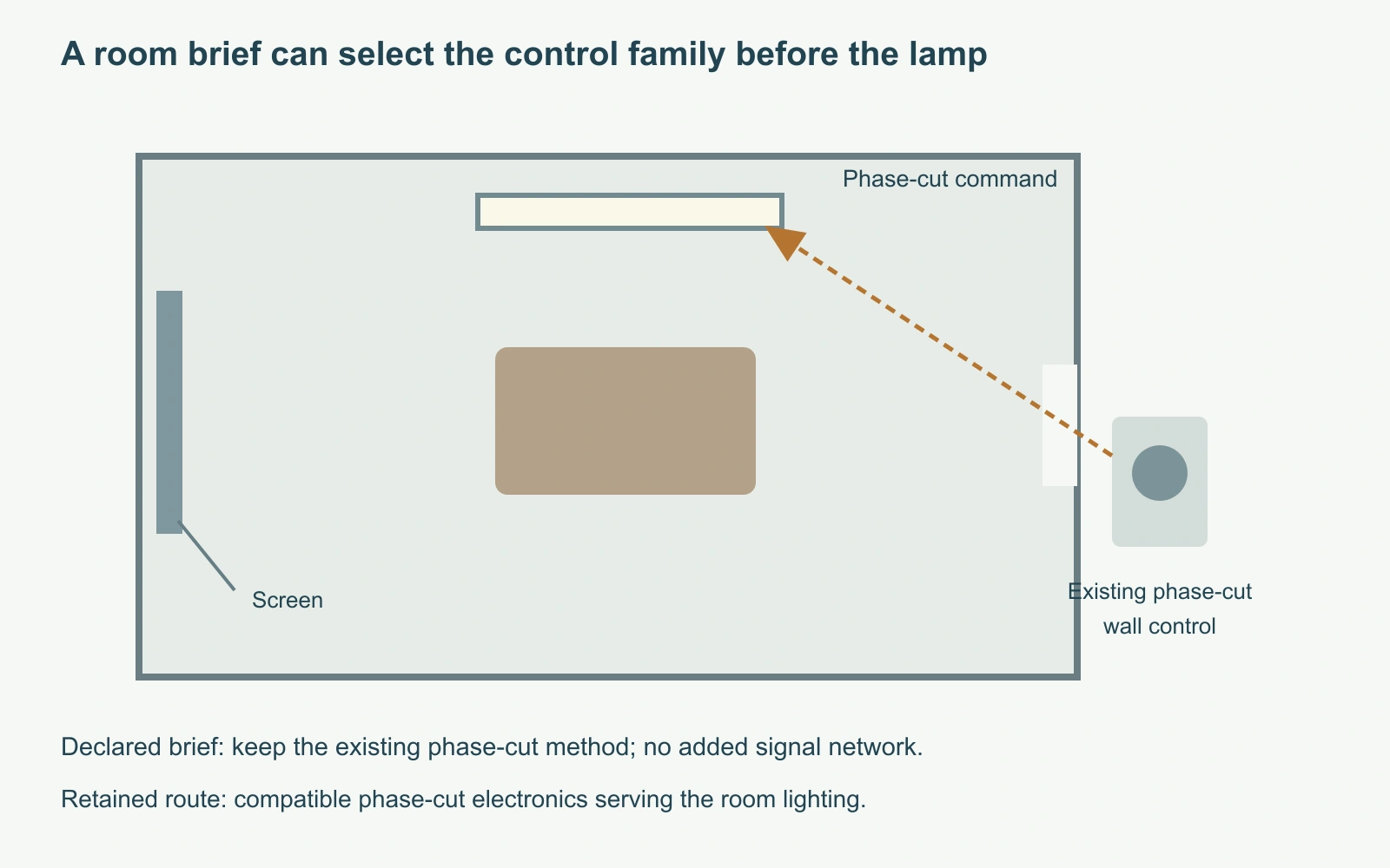
Consider a declared planning example: a presentation room has an existing phase-cut control, adjustable note-taking light is required, and adding a separate control network is outside the work scope. No specific controller or accepted lamp is assumed.
The available command travels through the existing control path. A driver that requires only a separate 0-10V signal, or only a digital interface, cannot satisfy that brief merely because its tube fits the ceiling fixture.
Selecting the route that preserves the intended operation
The useful shortlist is therefore a phase-cut-compatible electronic route with applicable pairing evidence. Then establish the supported lamp quantity and the startup, transition and off behavior needed by the room. If no suitable combination can be evidenced, the scope must change: retain simple switching, change the controls or evaluate another lighting assembly. The control family is defined at this point; a particular lamp enters the confirmed shortlist when its combination evidence is available.
Keep later replacements consistent with that control path
For the declared room, preserve the supported command path when ordering replacements. Model size, white appearance and power still matter, but the electronic version is part of the replacement identity. This is where control selection affects purchasing and maintenance rather than remaining an abstract protocol discussion.
| Candidate direction | Outcome | Reason |
|---|---|---|
| Documented phase-cut combination | Continue the shortlist | Uses the available command path |
| 0-10V-only or digital-only driver | Requires a changed control scope | The required command path is absent from the declared brief |
| Matching tube size with unknown electronics | Physical candidate only | Mechanical fit does not identify control behavior |
The LED tube flicker resource covers symptoms when an installed system behaves unexpectedly. For a new specification, resolving the intended control relationship first is a more direct route to the lighting scenes you need.