
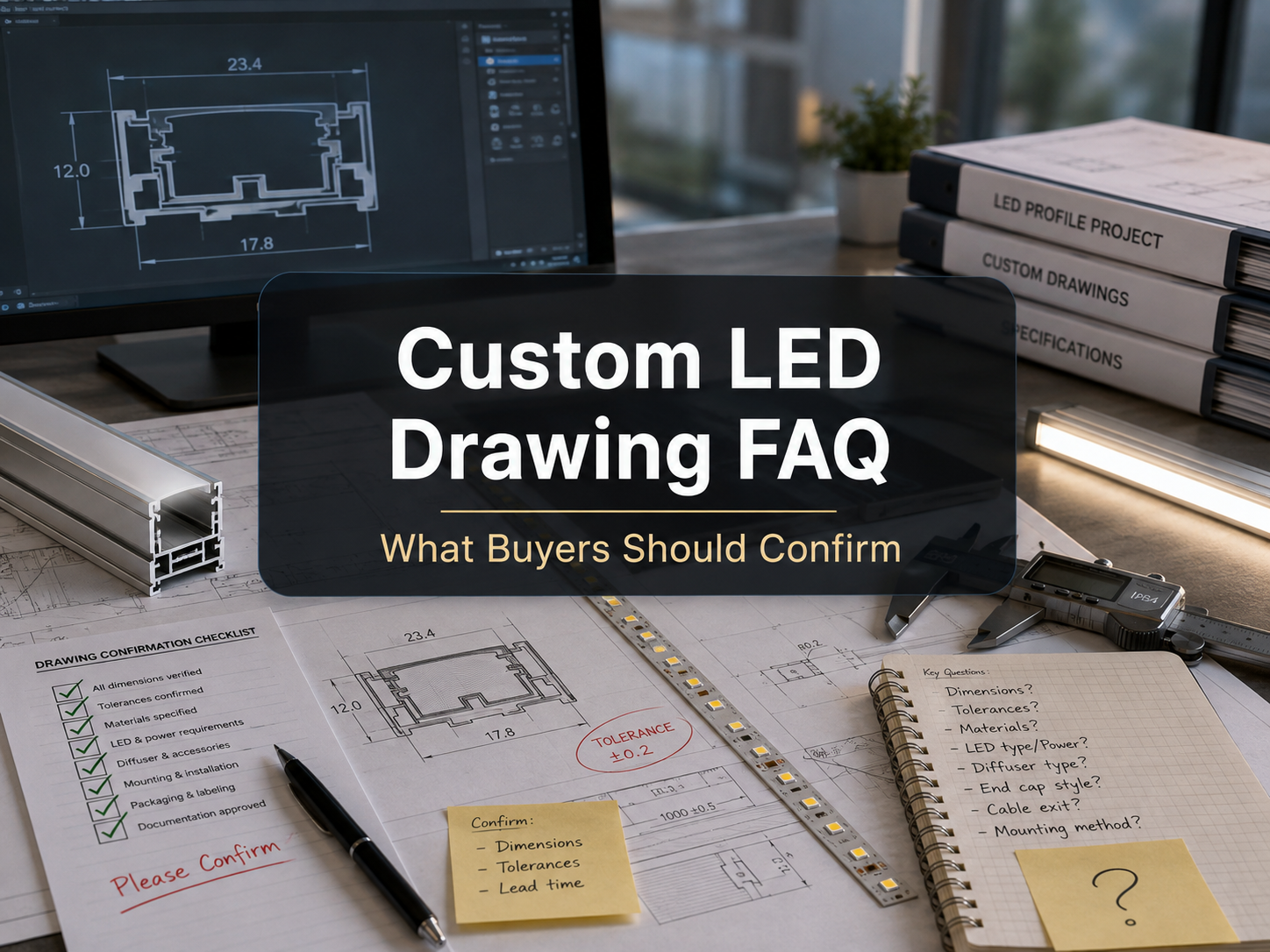
Before sending a custom LED drawing, you should confirm the electrical input, optical target, product dimensions, installation method, driver and dimming requirements, cable routing, environmental rating, material limits, testing needs, and compliance requirements. These details allow the supplier to quote the correct design, avoid unsafe assumptions, and identify production risks before samples are made.
Drawing Scope and Basic Project Information
What should a custom LED drawing include before it is sent to a supplier?
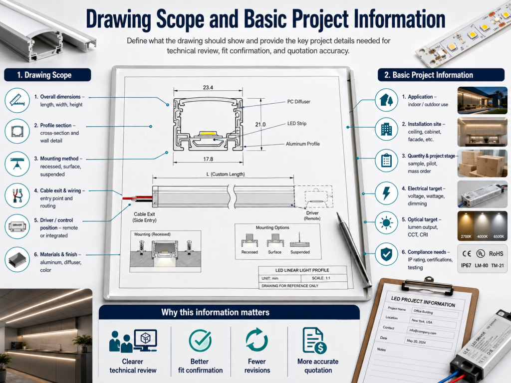
A custom LED drawing should include the product size, LED layout, electrical input, wattage target, color requirements, mounting method, cable details, connector type, IP rating, and application environment. The drawing does not need to be perfect, but it must show enough information for technical review.
For example, a linear LED module drawing should show overall length, PCB width, LED pitch, cut position if any, wire exit direction, lens or diffuser requirement, and installation hole locations. If the drawing only shows the outline size, the supplier must guess the electrical design, optical output, and assembly method. That usually leads to quotation revisions or sample changes.
Why is the application environment important for a custom LED drawing?
The application environment defines the protection level, material choice, heat dissipation, cable type, and safety margin. Indoor furniture lighting, outdoor signage, refrigeration lighting, and machinery integration all need different design assumptions.
If the LED will be installed in a sealed metal channel, the thermal path may be better than in a plastic cavity. If the product is installed outdoors, the drawing should mention rain exposure, UV exposure, condensation risk, operating temperature, and whether an IP65, IP67, or higher solution is expected. These details affect cost, lifetime risk, and warranty evaluation.
How much detail is needed for quotation versus sample production?
A quotation needs enough detail to estimate materials, labor, testing, and production feasibility, while sample production needs final dimensions, tolerances, wiring, labels, and performance targets. A rough drawing can support budget pricing, but it is not enough for reliable production.
For quotation, suppliers usually need product type, quantity range, voltage, wattage, CCT, CRI, size, IP rating, driver requirement, cable length, connector type, and installation environment. For sampling, the drawing should also confirm mechanical tolerances, LED binning, adhesive or mounting accessories, packaging, test criteria, and approval standards.
| Drawing Item | Why It Matters | Example Confirmation |
|---|---|---|
| Overall dimensions | Controls PCB, housing, diffuser, and installation fit. | Length 500 mm, width 12 mm, tolerance plus or minus 0.5 mm. |
| Electrical input | Defines driver selection, current, wire size, and voltage drop risk. | 24 V DC constant voltage input, 9.6 W per meter. |
| Optical target | Controls LED selection, density, binning, and diffuser design. | 3000 K, CRI 90, target 800 lm per meter. |
| Mounting method | Affects holes, clips, adhesive, heat transfer, and service access. | 3M adhesive plus aluminum profile mounting. |
| Environment | Defines IP rating, material choice, sealing, and operating temperature. | Indoor cabinet, dry location, 0 to 40 degrees Celsius. |
Electrical and Optical Specification Questions
What voltage, wattage, and current details should buyers confirm?
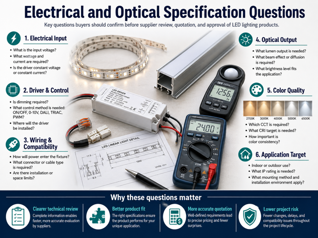
You should confirm the input voltage, total wattage, wattage per meter or per module, and expected current. These values are the foundation for PCB design, driver selection, cable sizing, connector choice, and safety evaluation.
Voltage means the electrical potential supplied to the LED product, such as 12 V DC, 24 V DC, or constant current input. Wattage is the power consumed by the LED product. Current is calculated from power and voltage for constant voltage products. For example, a 24 V LED strip rated at 48 W draws about 2 A. If the drawing does not state these values, the supplier cannot correctly evaluate wire gauge, voltage drop, or driver capacity.
Should luminous flux and luminous efficacy be included in the drawing?
Yes, luminous flux and luminous efficacy should be included when brightness performance matters. Luminous flux is the total light output in lumens, while luminous efficacy is lumens per watt.
A drawing that only states wattage does not define brightness. Two LED designs with the same wattage can produce different lumen output due to LED type, CCT, CRI, diffuser loss, thermal condition, and drive current. If a retail shelf light needs 900 lm per meter after diffuser loss, that target should be stated clearly. This helps avoid samples that meet electrical power but fail the visual or photometric requirement.
What color parameters should be confirmed before quotation?
You should confirm CCT, CRI, color tolerance, and any binning requirement before quotation. These color parameters affect LED selection, visual consistency, cost, and lead time.
CCT, or correlated color temperature, describes the light color appearance, such as 2700 K, 3000 K, 4000 K, or 6500 K. CRI, or color rendering index, indicates how accurately colors appear under the light. SDCM describes color consistency, where a lower SDCM value means tighter visual matching. For furniture, retail, hospitality, or architectural projects, a 3 SDCM or 5 SDCM requirement can be important for consistent appearance across batches.
How should beam angle, diffuser type, and LED spacing be shown?
The drawing should show the required beam angle, diffuser or lens type, and LED spacing if the visual effect matters. These details affect glare, hotspot control, uniformity, and mounting distance.
For example, a shallow cabinet profile may need close LED spacing and a frosted diffuser to avoid visible dots. A signage module may need a wide beam angle to spread light evenly across the panel. If the drawing only states brightness, the supplier may select a design that meets lumen output but creates hotspots or uneven illumination in the final installation.
Technical Factors to Check Before Releasing the Drawing
What mechanical dimensions and tolerances should be confirmed?
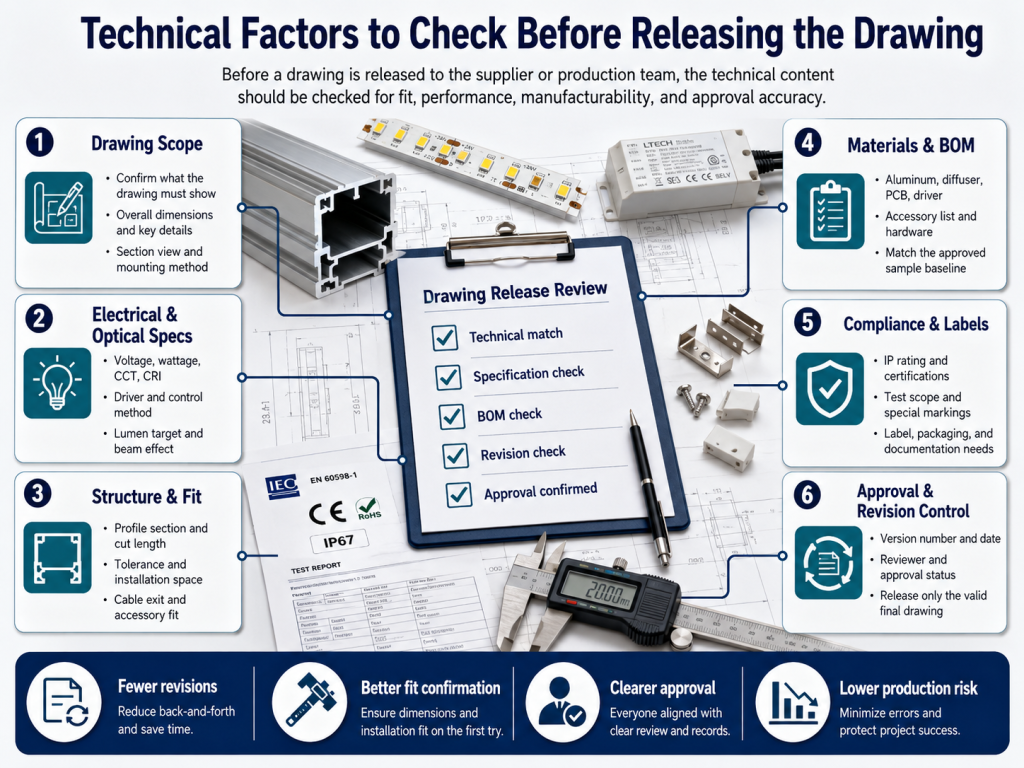
You should confirm overall dimensions, PCB width, hole positions, connector clearance, cable exit direction, bending limits, and assembly tolerances. Mechanical mismatch is one of the fastest ways to delay installation.
If the LED product fits inside a profile, channel, furniture groove, machine cavity, or signage housing, even a small width or connector error can prevent installation. The drawing should define critical dimensions separately from non-critical dimensions. Critical dimensions may need tighter tolerance, while cosmetic or flexible areas may allow wider tolerance to reduce manufacturing cost.
How should cable length, connector type, and wire exit direction be specified?
Cable details should include length, wire gauge, polarity, connector model, stripping length if needed, and exit direction. These details affect installation speed, voltage drop, service access, and field wiring accuracy.
For constant voltage LED products, long cable runs increase voltage drop, especially at low voltage and high current. A 12 V design is more sensitive to voltage drop than a 24 V design at the same wattage. If the drawing includes cable routing and driver distance, the supplier can recommend a suitable wire gauge, power feed location, or parallel wiring method.
What driver and dimming information should be confirmed?
You should confirm whether the product needs constant voltage or constant current input, the driver output rating, and the dimming method. Driver mismatch can cause flicker, reduced brightness, overheating, or early failure.
Dimming methods may include PWM dimming, 0 to 10 V, DALI, TRIAC, DMX, or smart control systems. The drawing should state whether dimming is required and where the dimming control is located. If the product will connect to an existing driver, provide the driver model, output voltage or current, wattage capacity, dimming protocol, and wiring diagram.
What IP rating and environmental protection details should be included?
The drawing should include the required IP rating and the real exposure conditions. IP rating describes protection against dust and water, but it does not explain every environmental risk by itself.
For example, IP65 may be suitable for water spray, while IP67 may be needed for temporary immersion conditions. Outdoor products may also need UV-resistant materials, corrosion-resistant parts, drainage planning, and suitable potting or sealing. For industrial equipment, oil mist, vibration, and chemical exposure may matter more than rain. The drawing should describe the actual environment, not only the IP number.
| Technical Factor | Confirm Before Sending Drawing | Project Risk If Missing |
|---|---|---|
| Voltage and current | Input voltage, total wattage, current, and power feed method. | Wrong driver, voltage drop, overheating, or unstable operation. |
| Color quality | CCT, CRI, SDCM, and binning requirement. | Visible color mismatch across fixtures or production batches. |
| Mounting space | Profile size, hole position, adhesive area, clip type, and access space. | Installation rework, poor heat transfer, or blocked maintenance access. |
| Dimming control | PWM, 0 to 10 V, DALI, TRIAC, DMX, or non-dimming requirement. | Flicker, incompatibility, or control system failure. |
| Protection rating | IP rating, IK rating if needed, condensation risk, and temperature range. | Water ingress, material degradation, or premature failure. |
| Compliance need | UL, ETL, CE, RoHS, EMC, IEC, or local code requirement where applicable. | Approval delay, redesign cost, or import and installation restrictions. |
Pro Tip: Before requesting a custom LED quotation, mark the drawing with “must match” dimensions and “adjustable” dimensions. This small step helps engineering teams protect critical installation fit while allowing practical manufacturing changes. It can reduce sample revisions, especially when the LED assembly must fit into a fixed aluminum profile, furniture groove, machine panel, or existing housing.
Installation, Thermal Management, and Reliability Questions
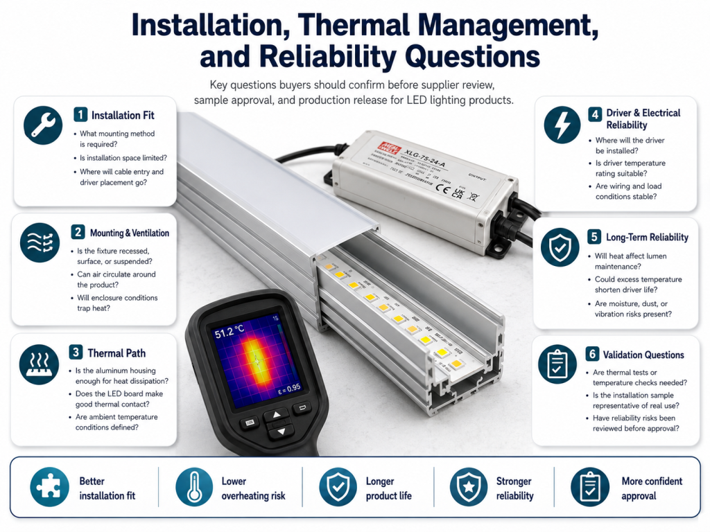
Why should the mounting method be confirmed in the drawing?
The mounting method should be confirmed because it affects mechanical strength, heat dissipation, alignment, and future maintenance. Adhesive tape, screws, clips, magnets, and aluminum channels all behave differently in real installations.
For example, high-power LED strips should not be applied directly to low-conductivity plastic if heat cannot escape. A rigid LED bar may need screw holes or clips to prevent movement. If the installer must replace the product later, the drawing should avoid hidden fasteners or inaccessible connectors. Good mounting information reduces installation time and service risk.
What thermal management details should be included?
You should include expected operating temperature, mounting surface material, airflow condition, housing type, and any heat sink requirement. LED performance and lifetime are strongly affected by heat.
Thermal management means controlling heat generated by LEDs, resistors, drivers, and enclosed assemblies. If the LED module is installed in a sealed box, narrow channel, or high-temperature equipment cabinet, the design may need lower wattage, aluminum backing, thermal tape, wider PCB copper area, or a separate heat sink. Without thermal information, the quoted design may work in open air but fail in the final installation.
How should maintenance access be considered in a custom LED drawing?
Maintenance access should be shown through connector location, replaceable module design, screw access, and service clearance. A product that is easy to install may still be expensive to repair if maintenance access is ignored.
In retail displays, furniture, and equipment integration, LED products are often installed behind panels, diffusers, or decorative covers. If the cable connector is hidden behind a fixed part, replacement may require dismantling the whole structure. A drawing should show how the LED product will be removed, disconnected, and replaced if failure or upgrade occurs.
Compliance, Testing, and Quotation Questions
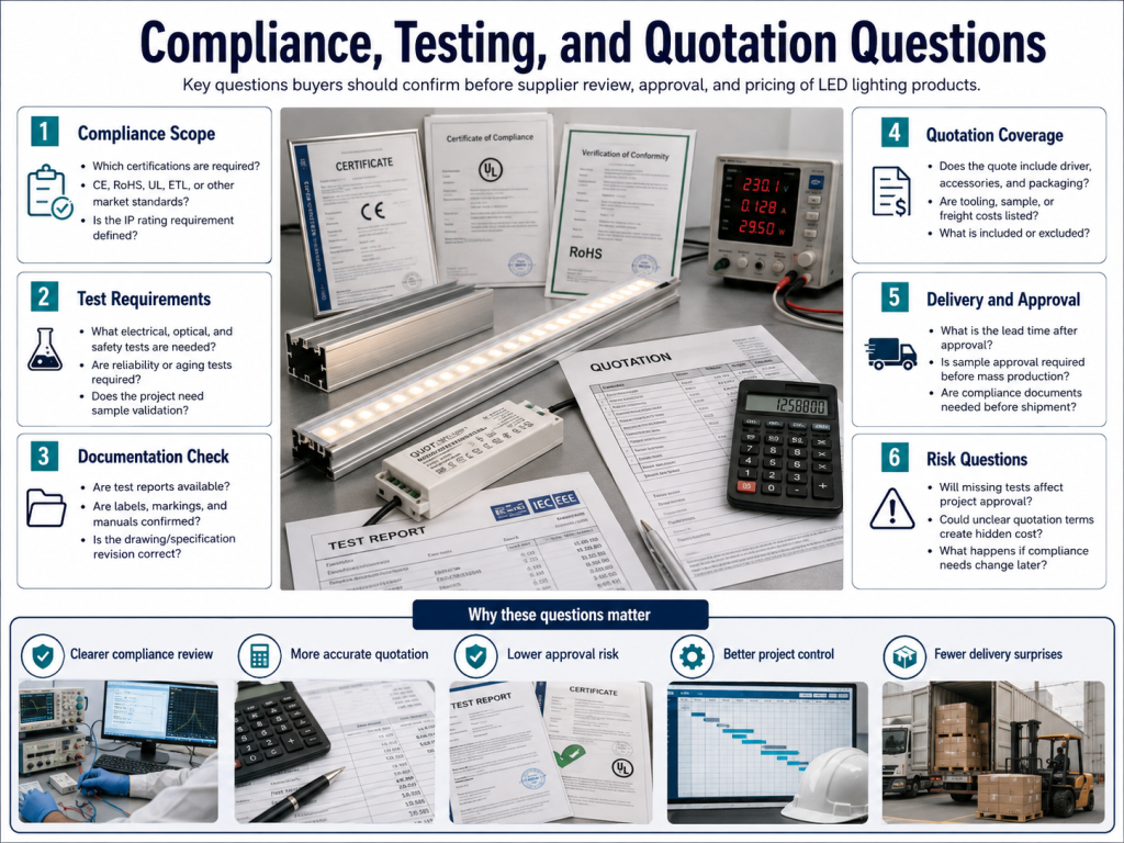
Which certifications or compliance requirements should be stated?
You should state any required certification, safety standard, EMC requirement, environmental restriction, or local electrical code requirement before quotation. Compliance affects component selection, driver choice, labeling, testing, documentation, and lead time.
Depending on the market and product type, buyers may ask about UL, ETL, CE, RoHS, REACH, EMC, IEC standards, or local installation rules. Photometric data may require LM-79 style testing, while LED lifetime evaluation may reference LM-80 and TM-21 data from LED packages. Do not assume certification is included unless it is confirmed in the quotation scope.
What testing or inspection requirements should be included?
The drawing or RFQ should state the required electrical, optical, mechanical, and environmental tests. Testing requirements help define acceptance criteria before production begins.
Common checks may include input voltage test, power consumption test, polarity check, burn-in test, CCT and CRI measurement, lumen output test, visual inspection, IP test where applicable, adhesive strength check, connector pull test, and packaging inspection. If you need a test report, specify the format, sample size, test equipment requirement, and acceptance tolerance.
How do MOQ, lead time, and custom tooling affect the drawing review?
MOQ, lead time, and tooling should be confirmed because custom drawings may require dedicated PCB layouts, molds, diffusers, cables, labels, or fixtures. These items can change quotation cost and production schedule.
A small change in width, connector location, lens shape, or housing profile can move a project from standard modification to custom tooling. If the buyer needs a short lead time, it may be better to adapt the drawing to an existing PCB, profile, connector, or driver platform. This should be discussed before finalizing the drawing.
What are the most common drawing problems that delay quotation?
The most common problems are missing electrical values, unclear dimensions, undefined CCT and CRI, no installation environment, unspecified cable details, and missing driver information. These gaps force the supplier to ask follow-up questions before costing the product.
Quotation delays also happen when the drawing shows a mechanical concept but does not define whether the product is an LED strip, rigid module, light bar, panel, or complete fixture. Clear product scope helps the supplier separate LED assembly cost from driver, mounting accessory, packaging, testing, and certification cost.
| Quotation Checklist Item | Recommended Confirmation |
|---|---|
| Product scope | Confirm whether the quote is for LED PCB only, LED module, light bar, driver kit, or complete lighting assembly. |
| Performance target | Confirm voltage, wattage, lumen output, CCT, CRI, SDCM, and beam requirement where relevant. |
| Installation fit | Confirm critical dimensions, tolerances, mounting method, cable direction, and connector clearance. |
| Environment | Confirm indoor or outdoor use, IP rating, operating temperature, humidity, UV exposure, and vibration if applicable. |
| Commercial scope | Confirm quantity range, sample quantity, target lead time, packaging, labeling, and any testing report requirement. |