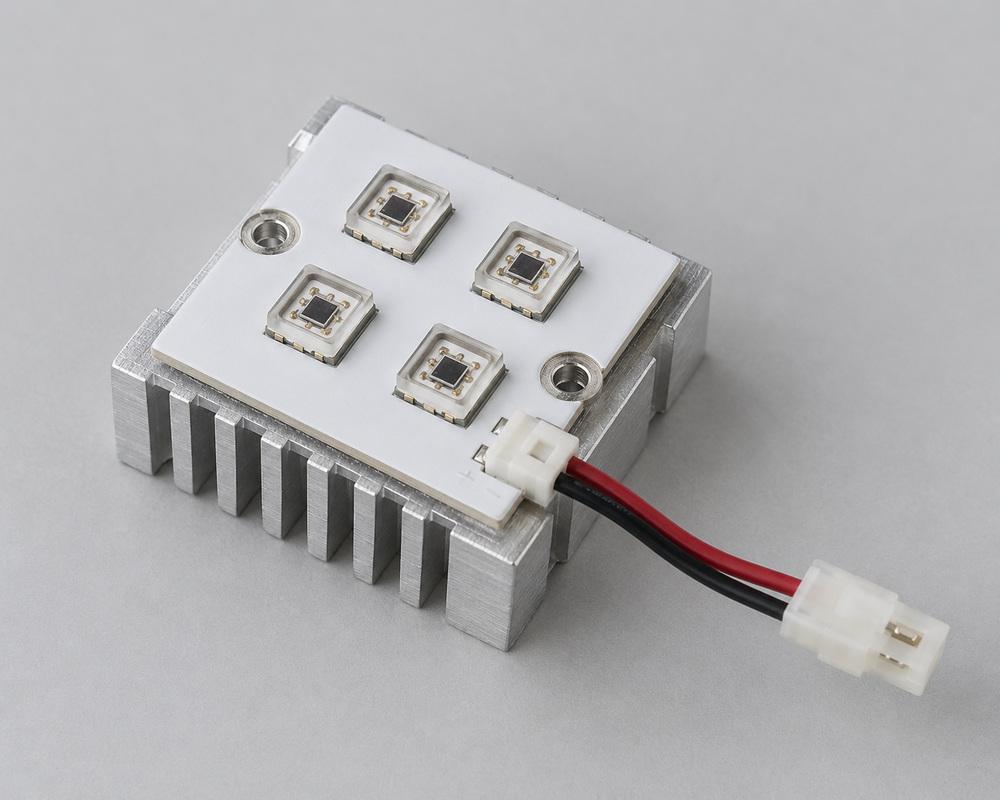
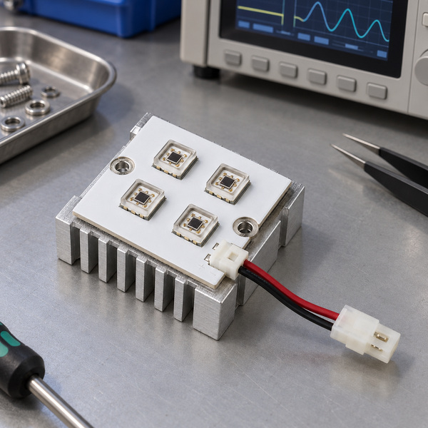
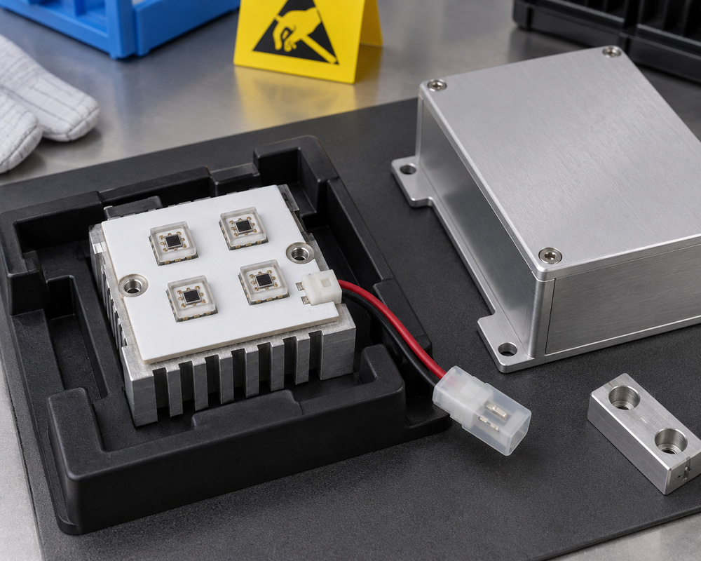
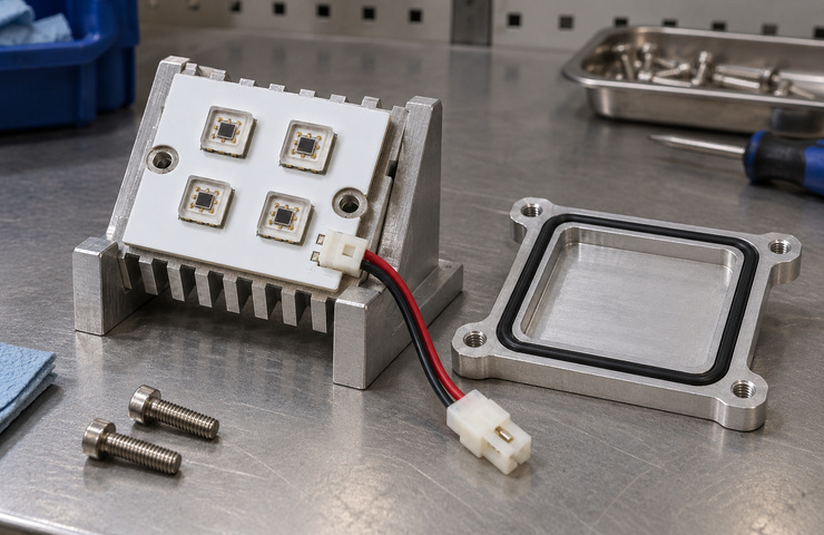
A UVC LED module needs effective heat transfer, a suitable driver, and a protected optical path inside the equipment. VST can discuss your requirements and assess development feasibility using its general module-integration experience. UV measurement, exposure assessment, and treatment validation require suitable specialist resources and agreed responsibilities before work is commissioned.
Board, mounting, and driver connections specified together
UV measurement requirements and responsibilities defined before testing
Enclosure protection and shutdown responsibilities identified
Describe the enclosed application, intended module space, and treatment objective; identify any operating conditions that remain undecided.
Install the UV source inside a protected host
A UVC LED module may suit the enclosed equipment concepts below. Each host needs optical and safety assessment. The illustrations show possible layouts and provide no evidence of a completed device or treatment effectiveness.
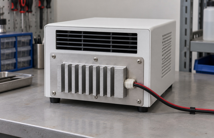
Enclosed air-treatment unit
Operating environment
Opaque equipment chamber with a baffled airflow path
Buyer requirement
Integrate the source while preventing exposure through accessible openings.
Design constraint
Airflow and enclosure geometry determine treatment conditions.
Design direction
Place the light engine within a protected optical zone with a separate dry driver area.
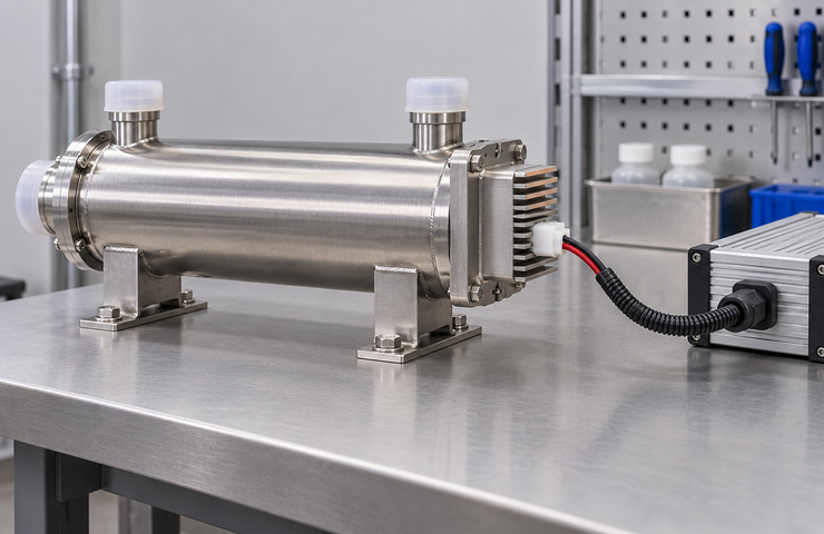
Closed water-treatment reactor
Operating environment
Sealed fluid chamber and dry electrical compartment
Buyer requirement
Keep the module outside the fluid path while establishing its optical interface.
Design constraint
The chosen window and seal must suit the system construction.
Design direction
Evaluate the dry source-to-reactor connection with the board outside the water path.
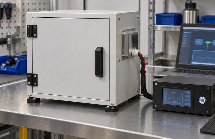
Automated enclosed process cabinet
Operating environment
Source operates within an inaccessible process volume
Buyer requirement
Connect irradiation and shutdown behavior to the host operation.
Design constraint
Opening and maintenance states affect exposure control.
Design direction
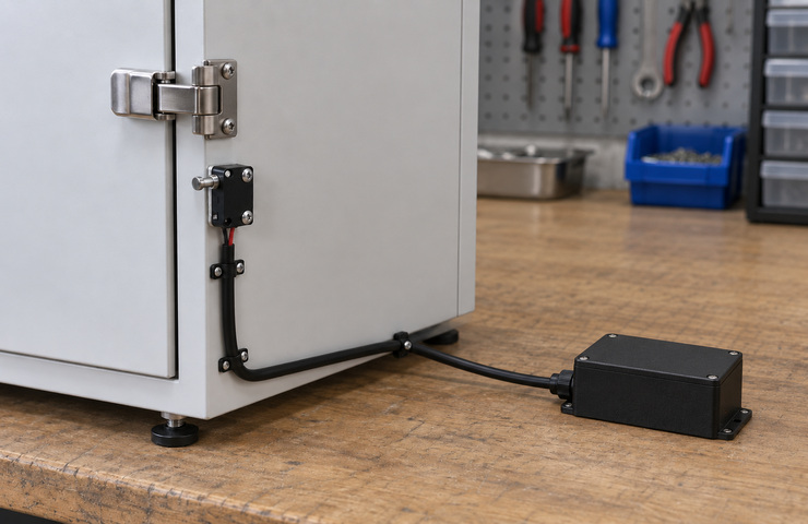
Keep the source inside an opaque enclosure with an appropriately defined shutdown interface.
Check UV output, thermal contact, and exposure control
Visible brightness is treated as evidence of UV output
Purchasing risk: A visible glow or lumen figure cannot establish the required UV-C radiant characteristics.
Confirm: Target spectral band and optical assessment scope
VST solution direction: Identify the wavelength, radiant-flux target, measurement conditions, and qualified test provider needed for the source objective.
The module is mounted without an effective thermal contact
Purchasing risk: Operating temperature can change source behavior and stress components.
Confirm: Permitted heat-transfer path in the host
VST solution direction: Assess the available heat-transfer contact and driver conditions before deciding whether module development is feasible.
An enclosed product is assumed safe without assessment
Purchasing risk: Accessible openings or faulty shutdown behavior can create a separate system risk.
Confirm: Host exposure-control responsibility and maintenance states
VST solution direction: Identify the complete-equipment exposure assessment needed to support safe-use and compliance claims.
A UVC LED module feasibility discussion can cover the source board, thermal support, driver, and optical window. Each option needs suitable materials and an agreed route for UV and system assessment. The project must establish the wavelength, radiant output, operating conditions, and evidence required before development is accepted.
UV source and optical interface
Specify the requested peak wavelength and tolerance in nm, radiant flux in mW or W, drive current in mA or A, voltage in V, and the temperature and optical measurement conditions. Assess the source package, window material, and host geometry against those requirements before deciding whether UVC LED module development is feasible.
Buyer input: Proposed optical-window material at the host interface
Board and heat-transfer construction
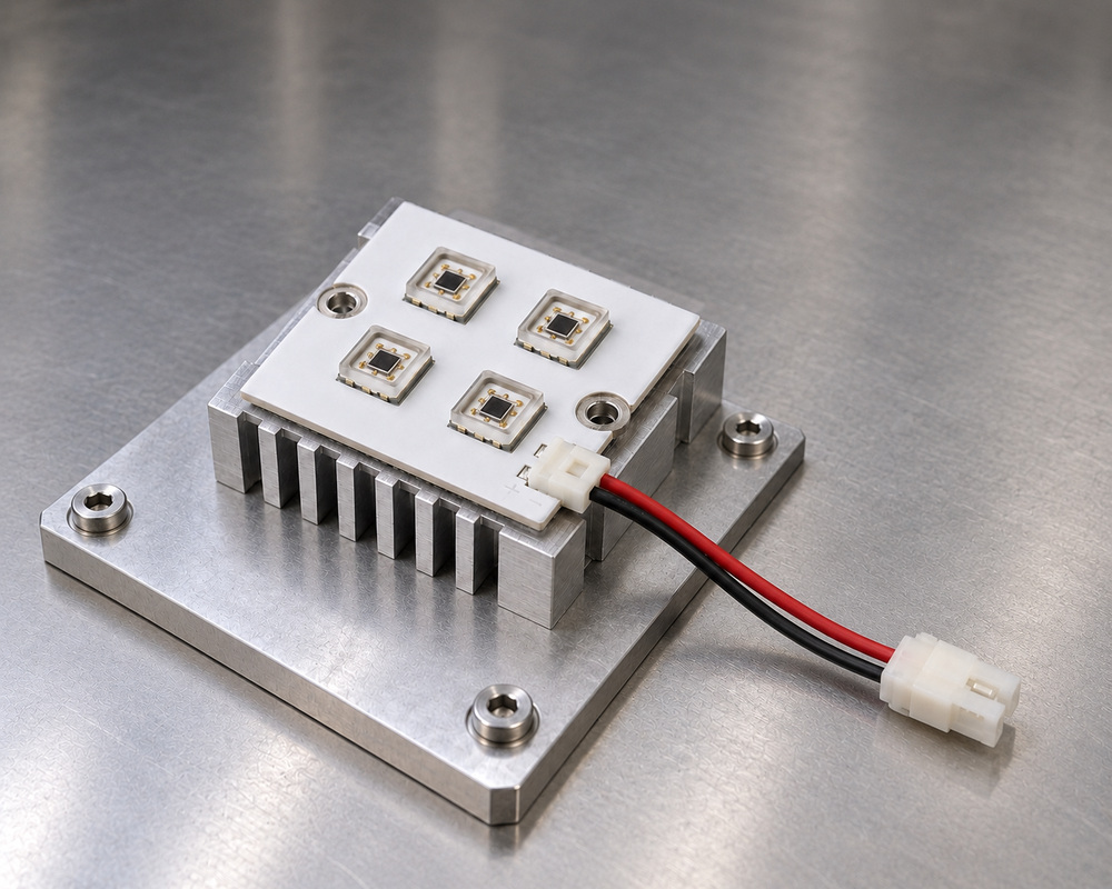
Board shape, fixing holes, and thermal support can be developed for the host. Maintain effective contact with the heat-transfer surface. A different board design may require dedicated PCB development or tooling.
Buyer input: Available mounting surface, fixing-hole constraints, and host thermal conditions
Driver and connection
Develop the circuit, lead, keyed plug, and external-driver connection for the electrical design. Specify circuit protection and operating states for that combination. An unrelated visible-light driver needs assessment before reuse.
Buyer input: Selected driver boundary and permitted fault response
Shutdown integration
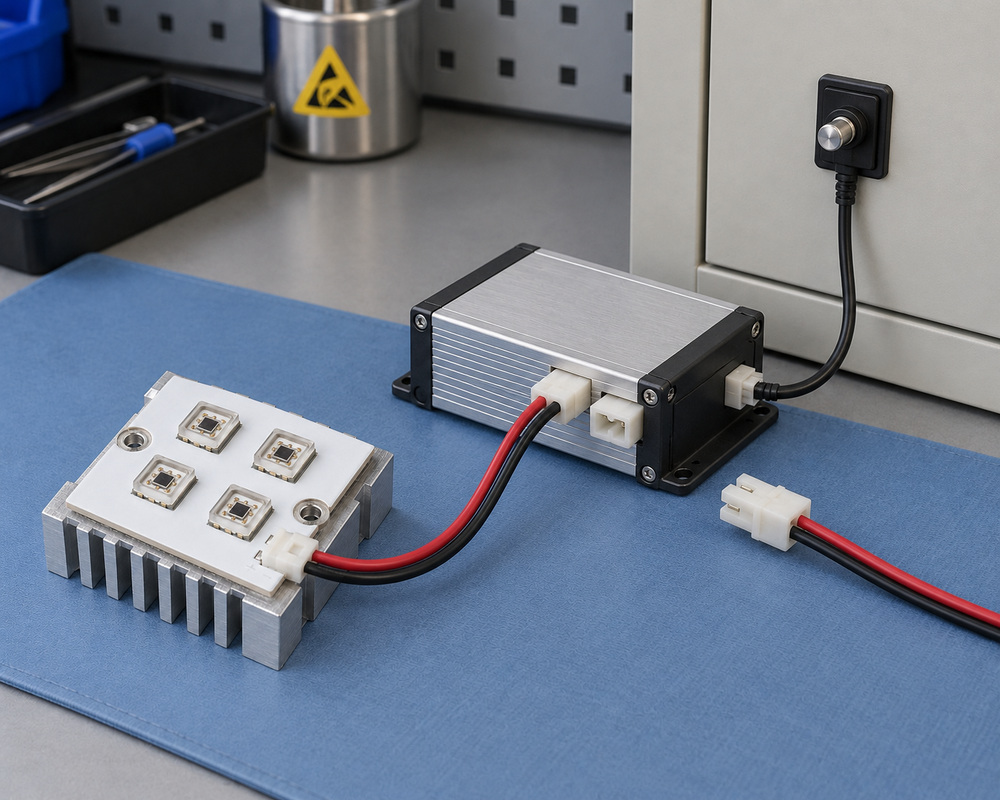
A host-interlock input can be discussed if supported by the equipment design. Exposure control also depends on the complete enclosure and switching behavior, with applicable system assessment of the connected arrangement.
Buyer input: Required shutdown input and restart behavior
The host medium affects the optical and mounting arrangement. Choose the equipment architecture before specifying the source installation. Treatment outcomes require evidence for the actual operating conditions in either arrangement.
Decision factor
Enclosed air-path source
Dry source behind reactor window
Buyer guidance
Optical boundary
Radiation enters a protected airflow volume
Radiation passes through the selected window into fluid
Account for the medium and optical interface in the system model.
Source placement and electrical separation
Source remains separated from accessible airflow openings
Board and driver remain outside the sealed fluid volume
Keep the board and electrical connections in a dry compartment.
Mechanical interface
Mounting follows duct or chamber support surfaces
Mounting follows the optical port and sealing construction
Choose a support arrangement consistent with the host enclosure.
System evaluation
Airflow conditions and exposure geometry affect treatment
Flow, optical transmission, and fluid conditions affect treatment
Use application-specific evidence before assigning a treatment-performance claim.
The first step is to assess whether the proposed UVC LED module can be developed for the host equipment. Identify the source requirements, optical window, driver, and thermal contact. Establish the technical evidence, specialist testing resources, and responsible parties before agreeing to samples, development, or application-performance claims.
01
Assess the source and host requirements
Customer input: Chosen equipment and validation boundaries
VST work: Identify source specifications, the driver, thermal contact, enclosure, and optical window for the feasibility assessment.
Stage output: A proposed module scope and unresolved specialist-assessment requirements.
02
Evaluate mounting feasibility
Customer input: Host mounting drawing and thermal-contact surface
VST work: Assess fixing positions and thermal contact on the proposed host. Plan a mechanical sample only after the development scope is accepted.
Stage output: A proposed mounting and thermal-contact check for a representative sample.
03
Specify driver and shutdown connections
Customer input: Driver operating limits and host shutdown/restart requirements
VST work: Identify circuit limits, connector pin functions, and required shutdown behavior. Agree who develops and validates the connected equipment.
Stage output: Proposed electrical interfaces and assigned system-validation responsibilities.
04
Agree the development decision
Customer input: Accepted construction and assessment responsibilities
VST work: Identify the technical records, UV-capable testing resources, and application evidence needed before committing to the module proposal.
Stage output: A development-feasibility decision and an agreed evidence plan.
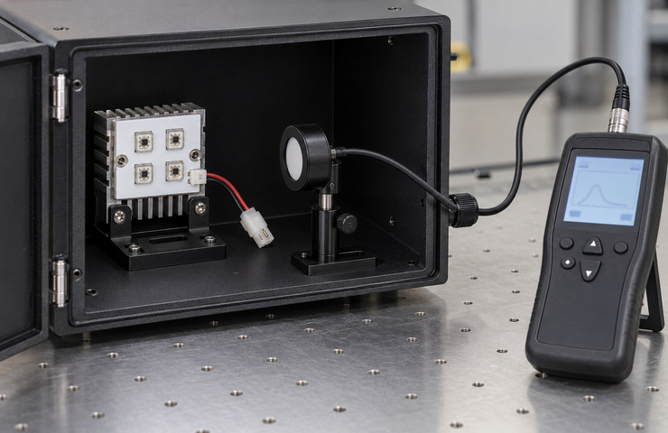
UVC LED modules require instruments calibrated for the radiation being measured. The checks below are proposed methods, subject to development feasibility and an agreed test plan. Confirm the instrument, calibration, test provider, and responsible project party before booking work. No existing UV measurement service, completed system validation, or passed treatment result is established here.
UV optical characterization
Purpose: Measure the required UV radiant characteristics.
Method: Arrange suitable UV-calibrated measurement for the selected source, spectral band, and enclosed measurement geometry.
Acceptance criteria: Measured wavelength (nm) and radiant flux (mW or W) meet the project limits at the specified drive current, voltage, temperature measurement point, and UV-calibrated optical setup. The responsible test provider and report format are agreed before testing.
Evidence: Confirm the UV-capable test provider, calibrated instrument, sample conditions, and report owner before testing. No UV measurement record is currently supplied.
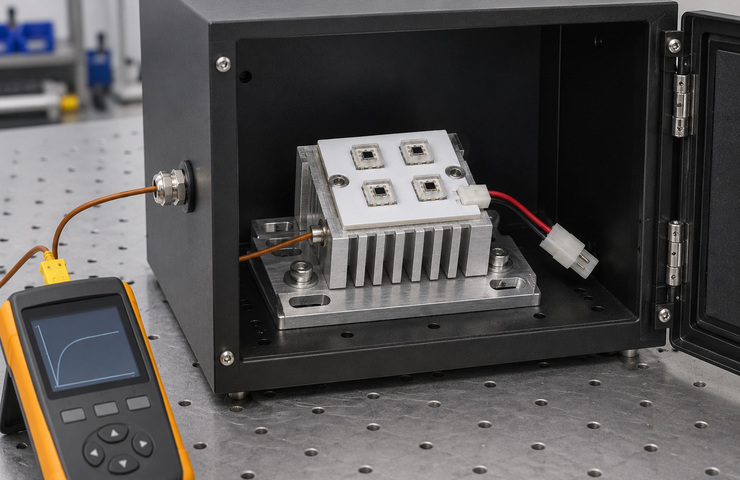
Module thermal interface
Purpose: Check the thermal condition of the source on its intended support.
Method: Measure appropriate contact temperatures with the module installed and operated inside a suitable protected test enclosure.
Acceptance criteria: Source and support temperatures remain within the selected component and design limits.
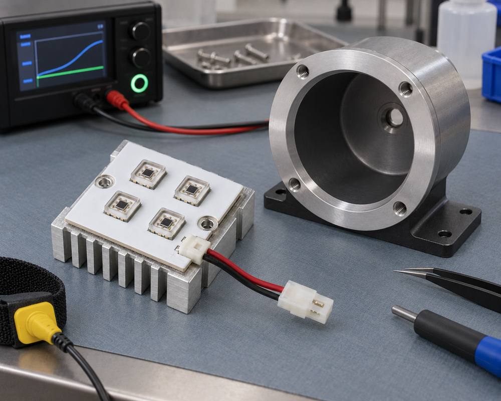
Evidence: The image shows setup preparation. Powered UV testing requires a suitable protected enclosure.
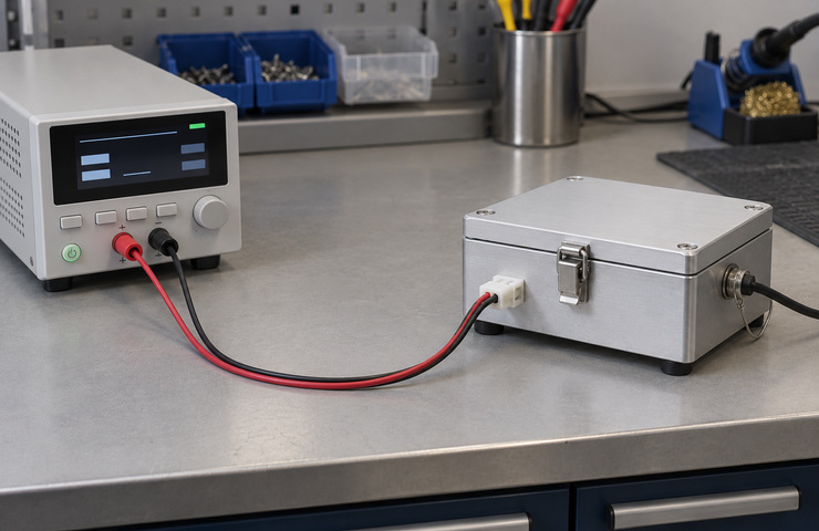
Driver and electrical load
Purpose: Check the source circuit against the proposed driver output.
Method: Measure the external electrical loop while the UV source operates within a closed protected enclosure.
Acceptance criteria: Current, load behavior, and selected operating states match the electrical definition.
Purpose: Check for interference where the dry source connects to the host.
Method: Inspect mounting contact, window-port alignment, and any selected sealing interface with the source unpowered.
Acceptance criteria: Parts seat correctly within the agreed mechanical arrangement without loading the electrical lead.
Evidence: Ingress and pressure ratings require their own applicable tests.
Shutdown-interface evaluation
Purpose: Check the intended response when the host enters a source-disabled state.
Method: Arrange evaluation of the connected interlock or shutdown interface within the closed protected equipment.
Acceptance criteria: The source-disable behavior follows the agreed architecture and requires applicable system assessment.
Evidence: Safety certification and fault-tolerant shutdown claims need applicable evidence.
Module documents and UV system evidence
Record the source design and identify the specialist measurements and application records needed for the finished equipment.
Module electrical and thermal interface
To Confirm
Request a source specification, driver and thermal-interface documents, proposed sample identification, and a UV test-responsibility matrix before accepting development.
UV and treatment assessment requirements
To Confirm
Identify the UV measurement provider, instrument calibration, exposure-assessment party, and treatment-validation owner. No specialist cooperation, system-validation, or UV delivery record is currently provided.
For general planning, the normal light-customization MOQ is 500 units for one model. The high-customization starting point is 1,000 units. Their applicability to a UVC proposal requires a feasibility and commercial decision. The quotation then records the source assembly, accepted development work, and actual quantity. No UV stock program is established by these figures.
Sampling support
UVC sample processing and any new mold or tooling charges need a project-specific agreement after feasibility is established. Confirm whether eligible sample expenses can be returned or credited toward later production, with the amount, qualifying order, and settlement method recorded. Specialist UV measurement, exposure assessment, and treatment validation have separate fees, providers, and responsibilities.
Lead-time factors
As general guidance, light samples use 15 to 25 working days and light bulk production 20 to 30; high-customization samples use 30 to 50 and high bulk production 25 to 35. Confirm applicability to the accepted UV proposal. Specialist measurement, system validation, and transport require separate fees and timelines. Timing begins with complete technical data and fulfillment of relevant sample payments, tooling payments, deposit, and other order conditions. Reserving materials can shorten repeat work. Delivery is not guaranteed by these production ranges.
Tooling / NRE
Source-board work, thermal tooling, mounting fixtures, or an optical interface may incur tooling or NRE costs. Confirm the UV project terms before development. Any eligible mold or tool amount used to offset a subsequent production payment requires an identified qualifying order, credited sum, and application method. General policy does not promise recovery for this application.
Supply stability
Repeat UV module supply requires an accepted design, component controls, and a route for handling critical source or driver changes. Forecasts and material reservations can be discussed in the order terms after feasibility is established. Confirm availability for each order and assess changes against the required technical evidence.
Packaging & logistics
Packing should protect source windows, board edges, and connector identification before equipment assembly. Custom options include brand artwork, labels, barcodes, carton marks, user manuals, and instruction sheets. Shipment coordination follows the agreement. Freight costs, packing quantities, destination fees, and transit durations depend on the specific shipment.
UVC LED modules form part of an electrical, optical, and protective system. These questions address treatment claims, intended use, measurement, and supply contents. Discuss unresolved treatment objectives or assessment responsibilities with VST before setting the development work. Safety approval, medical suitability, and application performance each require evidence for the equipment.
Does a UVC LED module establish a disinfection rate?+
Treatment rates depend on the application, target, geometry, exposure conditions, and medium. The claim needs system and application evidence for those conditions. A source description, package listing, or concept image cannot establish a disinfection rate.
Can this module be specified for medical equipment or open exposure?+
This proposal concerns enclosed integration. Medical use and open exposure require their own intended-use specification, exposure controls, assessment, and supporting evidence from the responsible equipment project. Neither medical suitability nor safe open-exposure conditions are established for the proposed source.
Can ordinary lighting measurements establish UVC LED module performance?+
UV performance needs evidence matched to the radiation band and intended claim.
Question
Needed evidence
UV source output
Applicable UV-calibrated optical measurement
Accessible exposure
Complete equipment exposure assessment
Treatment effectiveness
Application-specific validation
Visible-light lumen measurements cannot establish these UV characteristics or system outcomes.
Are the reactor, enclosure, and driver automatically included?+
The quotation identifies the light engine and any expressly included equipment. Reactors, enclosures, fluid-path parts, and external drivers are separate unless included in that quotation. Application images show integration concepts rather than a bundled finished treatment system.
Which specifications are needed to assess a UVC LED module proposal?+
For a UVC LED module, provide project requirements or actual sample data. Identify the specialist test provider and system-validation owner before accepting performance claims.
Specification
Information to provide
Wavelength
Peak wavelength and permitted tolerance (nm), or the required spectral band
Radiant flux
Target and limits (mW or W), with current, temperature, and UV optical measurement conditions
Electrical drive
Current (mA or A), voltage (V), driver limits, connector pinout, and shutdown behavior
Thermal contact
Mounting surface, heat-transfer design, temperature limit (°C), and measurement point
Optical window
Material, transmission data for the required wavelength band, geometry, and sealing responsibility
Validation responsibilities
UV instrument and calibration provider, exposure-assessment party, and application-treatment validation owner
Host application and validation scope
Air, water or surface duty; relevant operating and exposure conditions; target treatment criterion; and the named application-validation owner