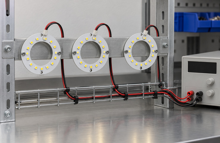
Custom LED Ring PCB Manufacturer for OEM Applications
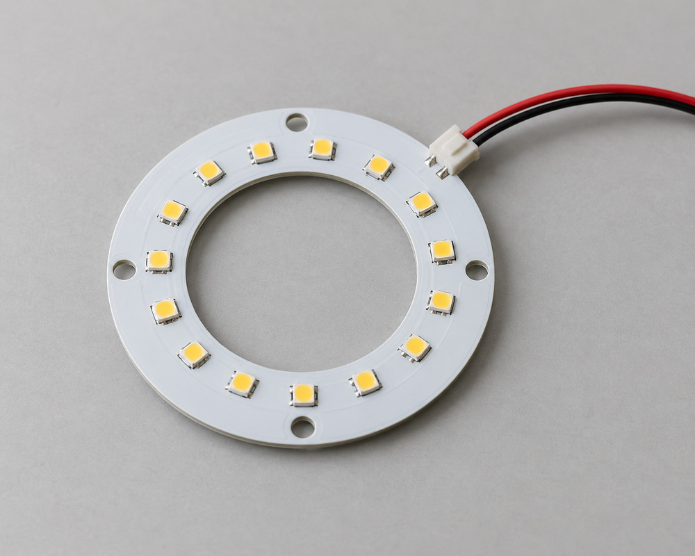
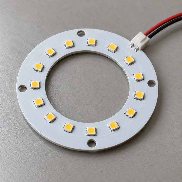
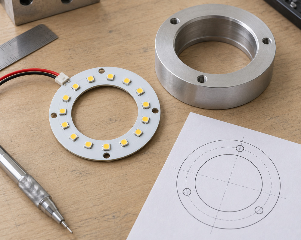
VST Lighting develops and manufactures custom LED ring PCBs for equipment manufacturers, lighting brands and OEM product developers. Our circular LED PCB solutions can be supplied as bare boards, populated LED assemblies, supported light engines or complete assemblies according to your project requirements.
From inner and outer diameter customization to LED layout, mounting holes, optical covers and electrical interfaces, we develop ring-shaped LED boards around the host product. Driver, controller, software and wiring integration can also be included within the agreed project scope.
OEM prototyping, assembly testing and repeat-production support
Custom ring PCB dimensions, LED placement and fixing arrangements
Circular lighting designs evaluated for optical uniformity, electrical compatibility and thermal support
Send your inner and outer diameter, lighting requirements, reference drawing and preferred assembly format for engineering review.
Custom LED Ring PCB Applications
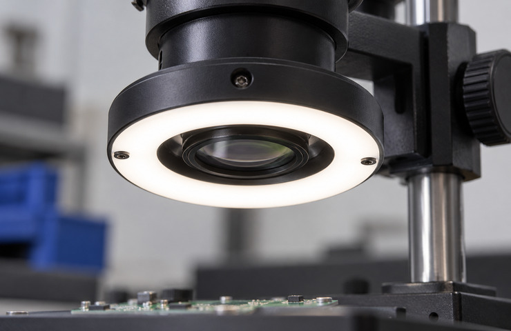
Ring-shaped LED PCBs provide circular illumination around a central opening, viewing path or product feature. These boards are commonly considered for equipment lighting, optical inspection assemblies and circular status indicators. VST evaluates the inner diameter, outer diameter, LED arrangement and available mounting space to help integrate the LED ring into the intended product.
Equipment viewing aperture
Operating environment
An indoor optical opening surrounded by a protected light source.
Buyer requirement
Illuminate the nearby working area while leaving the viewing path unobstructed.
Design constraint
The inner edge and cover can interfere with the usable aperture.
Design direction
Develop a supported ring behind a seated optical cover, leaving the central opening clear.
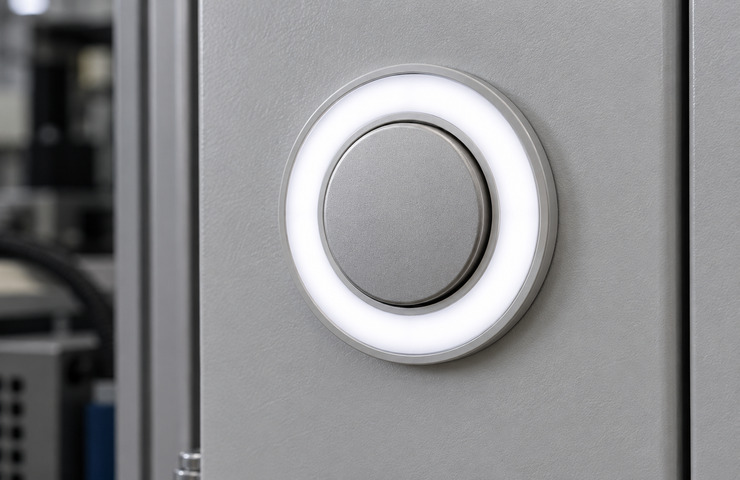
Circular status window
Operating environment
A complete indoor product panel with a diffused circular indication.
Buyer requirement
Provide a visible indication; independently controlled segments need to be specified separately.
Design constraint
Panel depth and the cover set the mixing space around the ring.
Design direction
A white-light ring can be evaluated with a continuous diffuser for simple indication.
Circular inspection head
Operating environment
An indoor equipment head illuminating a small nearby workpiece.
Buyer requirement
Place the source around the viewing axis and keep the view clear.
Design constraint
Nearby surfaces can reflect the ring into the optical path.
Design direction
Keep the board enclosed in its finished carrier and assess shielding from the viewing position.
Separate shape compatibility from functional compatibility
An opening that fits only at board level
Purchasing risk: Fasteners or the installed cover reduce clearance after assembly.
Confirm: Minimum clear opening through the assembled host
VST solution direction: Include the carrier and optical cover when checking the usable aperture.
A ring format mistaken for a controller interface
Purchasing risk: A control system may not drive the selected circuit correctly.
Confirm: Required channel behavior and controller output
VST solution direction: Decide whether the ring illuminates a task or indicates separate segments before choosing the circuit.
Connection collides with the host circumference
Purchasing risk: Lead handling can damage the board or prevent the cover seating.
Confirm: Connector keep-out within the circular carrier
VST solution direction: Locate the connection so the lead can exit clear of the fixing features.
Custom LED Ring PCB Design and Manufacturing Options
VST supports OEM LED ring PCB customization across circular board dimensions, LED population, optical arrangement, thermal support and electrical connections. Depending on project requirements, the design may involve selected PCB materials, SMD LED types, mounting-hole positions, LED spacing, input voltage, drive circuits and connection interfaces. The board geometry and lighting performance are evaluated together before the supplied assembly format is confirmed.
Annular outline
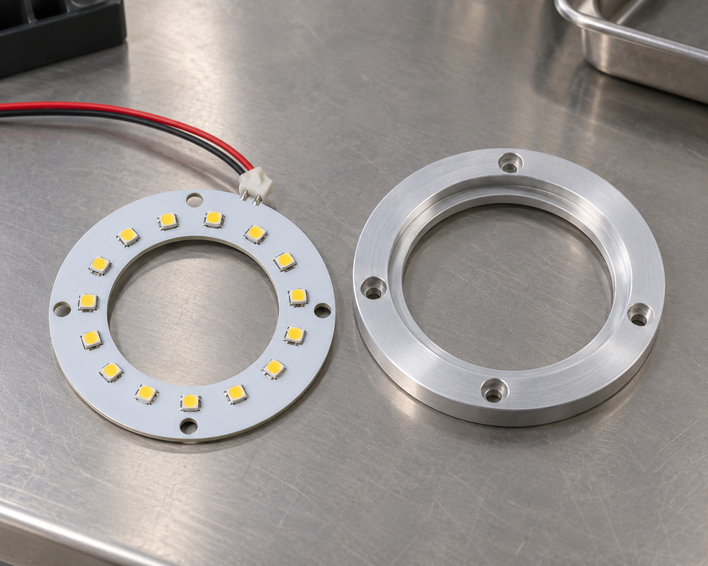
The inner diameter (ID), outer diameter (OD), ring width and mounting-hole layout define the usable space for a custom circular LED PCB. VST reviews the annular geometry against LED placement, circuit routing, connector clearance and the host product's locating features. The remaining PCB area must support the required circuit and mechanical arrangement without interfering with the central aperture.
Buyer input: Clear aperture and host locating surfaces
LED placement and cover
LED count, SMD LED spacing and optical orientation affect the brightness and visual uniformity of a ring-shaped LED PCB. VST can evaluate single-color and project-specific multi-channel arrangements according to the required lighting function. LED pitch, diffuser distance and the visible ring width should be reviewed together, because closely spaced LEDs do not automatically produce uniform illumination through the finished cover.
Buyer input: Cover profile and intended visible ring width
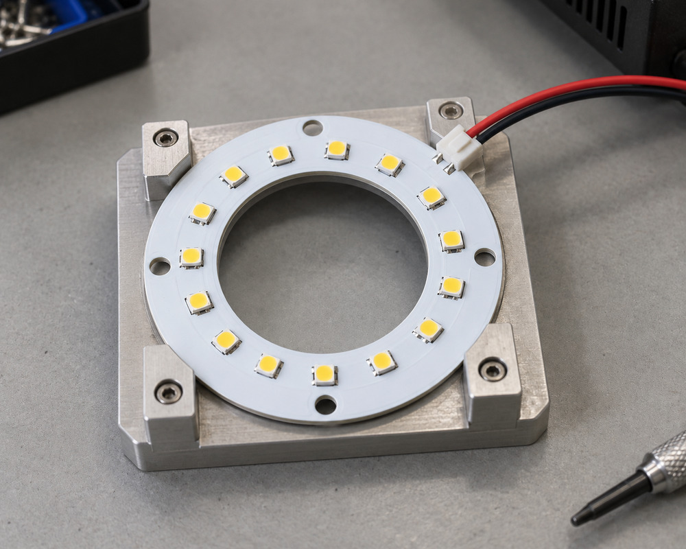
Carrier and heat path
LED count, SMD LED spacing and optical orientation affect the brightness and visual uniformity of a ring-shaped LED PCB. VST can evaluate single-color and project-specific multi-channel arrangements according to the required lighting function. LED pitch, diffuser distance and the visible ring width should be reviewed together, because closely spaced LEDs do not automatically produce uniform illumination through the finished cover.
Buyer input: Carrier contact and component-height limits
Drive, control and software interfaces
A custom LED ring PCB must match the host product's power supply and required lighting behavior. VST reviews operating voltage, current, connector pinout, channel configuration and applicable control requirements. Depending on the project, the supplied assembly may include compatible drivers, controllers, wiring harnesses or specified software and protocol development. RGB, segmented or independently controlled ring operation requires an appropriate circuit and controller design rather than a change in board shape alone.
Buyer input: Required lighting behavior, supply, host control interface, protocol and requested software deliverables
OEM buyers can source a custom LED ring PCB as a fabricated board, populated PCB assembly, supported light engine or complete lighting assembly. A bare PCB order requires the buyer to coordinate remaining LEDs, drivers, optics, wiring and mounting components as applicable. A more complete assembly can reduce the number of separate integration tasks, but the quotation must identify its included components and the remaining responsibilities of the host product manufacturer.
Decision factor
Bare or populated board
Supported light engine or complete assembly
Buyer guidance
Supplied parts
PCB fabrication, with LED population when specified
Board with the quoted support, cover, connections and additional electrical parts
Identify the included parts when comparing prices for different formats.
Host work
Define the remaining mounting, optics, thermal support and electrical work
Define the remaining host connections and installation access
The supplied assembly still needs a documented boundary with the host.
Controls and software
Driver, controller, software, protocol and harness are separately identified quoted items
These functions can be included in the agreed assembly scope
Describe the lighting behavior and host interface before selecting the control scope.
Sample acceptance
Check the board revision and the interfaces your host must complete
Check the assembled revision under its agreed support and electrical conditions
Use the specified sample format when setting acceptance and repeat-build requirements.
VST supports custom LED ring PCB development from the initial circular board outline through electrical design, sample assembly and production revision approval. The engineering process coordinates the central aperture, LED layout, mounting holes, thermal support and host connections. Where required, driver, controller, wiring and software development are defined within the agreed scope. Prototype checks establish whether the proposed ring assembly meets its intended mechanical and lighting requirements before repeat manufacturing.
01
Define the usable aperture
Customer input: Lighting function, inner and outer dimensions or a reference outline, fixing points and preferred supplied format.
VST work: VST develops the board outline and locating relationships around the central opening and the proposed host interfaces.
Stage output: An outline and supplied-format scope identifying the ring and host boundaries.
A reference board or sketch can be used while final dimensions are being established.
02
Develop board and support interfaces
Customer input: Supply and lighting behavior, source positions, cover requirements, support contact and control/software requirements.
VST work: VST develops the PCB and connections, and identifies the driver, controller, software, protocol and support parts to include.
Stage output: A proposed circuit and assembly scope with identified electrical and control interfaces.
Software and protocol deliverables are tied to the selected hardware and host system.
03
Build the ring sample
Customer input: The proposed interface revision, requested sample format and power/control equipment needed for evaluation.
VST work: VST builds the agreed sample and examines its opening, fixing, connection and operating behavior against the selected host interfaces.
Stage output: An identified ring sample and the findings from the agreed sample checks.
A bare-board sample and complete assembly require different acceptance scopes.
04
Set assembly controls
Customer input: The accepted sample revision, parts and software versions, required records and intended order format.
VST work: VST carries the PCB, LED population, support, harness and included control/software revisions into the supplied build definition.
Stage output: A released parts and assembly definition for the quoted format.
Later hardware or software changes are considered against the accepted revision.
Check the ring against its optical and electrical role
Evaluate an LED ring PCB for its intended function in the assembled host. The development checks below assess illumination and circuit compatibility on a specified sample. A circular outline cannot establish either result.
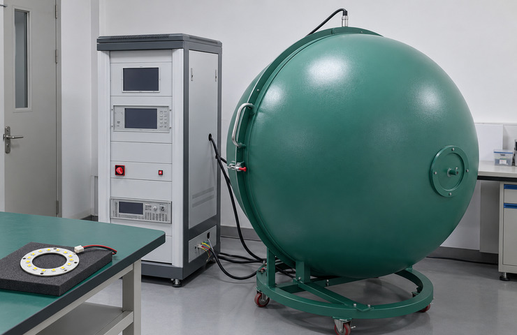
Total light and color
Purpose: Characterize the selected illumination ring without inferring performance from LED count.
Method: Measure the supported powered board in a closed integrating sphere at recorded operating settings.
Acceptance criteria: Required output and color characteristics for the specified illumination role.
Evidence: Project optical results are generated only after the agreed test on an identified circuit and sample revision.
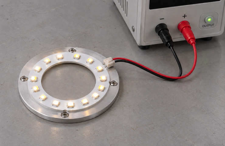
Supply and circuit operation
Purpose: Identify whether the ring works with its intended electrical source.
Method: Use a compatible regulated supply and instrumented circuit to observe operating voltage and current.
Acceptance criteria: Correct function within the board circuit and agreed supply limits.
Evidence: A project circuit record follows the agreed evaluation and identifies the connection and operating mode.
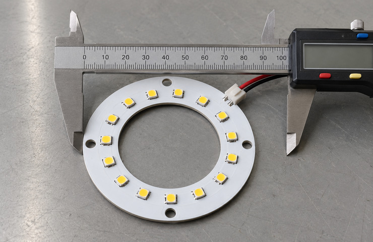
Aperture and fixing inspection
Purpose: Prevent interference with the viewing opening or host locating features.
Method: Check the annular outline and hole positions using a caliper and representative carrier.
Acceptance criteria: Clear aperture and fixing alignment within the project-defined fit requirements.
Evidence: Inspection observations are project-generated after the agreed checks against the ring outline revision.
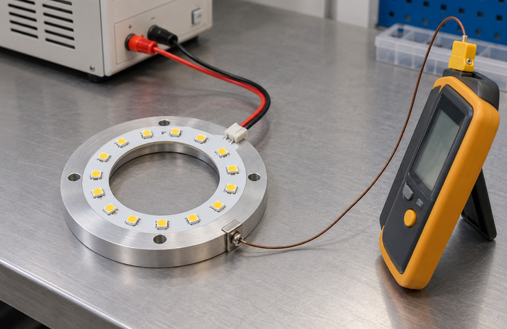
Mounted thermal behavior
Purpose: Evaluate heat transfer through the chosen ring support.
Method: Operate the sample on its carrier and log temperatures at the defined measurement locations.
Acceptance criteria: Relevant component and support temperatures under the intended mounting condition.
Evidence: A project thermal record follows agreed testing and includes the carrier and electrical setting.
Operating stability observation
Purpose: Observe continued function of the selected ring circuit.
Method: Run the supported ring samples in the agreed operating mode and record function and physical condition over the defined test period.
Acceptance criteria: Stable circuit function and acceptable physical condition against the ring specification.
Evidence: A ring-operation record is generated after the agreed observation period and records conditions and behavior; it is not a service-life result.
Define the ring circuit and outline
Ring outline and interface drawing
Project Specific
A project drawing can show aperture clearance, fixing positions and where the board connects to the host.
Circuit and host-control scope
Project Specific
VST can provide control hardware, software, protocol implementation and harnesses. The project scope identifies the included deliverables and the remaining host integration work.
VST provides project-specific quotations for bare LED ring PCBs, populated boards and complete OEM ring assemblies. Pricing, minimum order quantity (MOQ), prototype requirements and manufacturing lead times depend on board dimensions, PCB material, LED population, tooling, component sourcing and the agreed assembly scope. Share your required specifications, estimated order volume and target production schedule for a more accurate quotation.
Sampling support
The sample scope identifies the board revision, LED population and any support, cover, driver, controller, software or harness required for evaluation. Specify which interfaces must be represented and what acceptance findings are needed. Sample work and charges are quoted against that selected format.
Lead-time factors
Layout development, component sourcing, control or software work, sample revisions and evaluation can affect the schedule. Separate these tasks from repeat board fabrication and assembly. VST sets the sample and production plan for the selected LED ring PCB scope after its development and evaluation tasks are defined.
Tooling / NRE
Separate PCB design, software or protocol development, prototype assembly and dedicated tooling from the recurring unit price. The quotation identifies the development charges and any agreed credit arrangements. A bare-board price cannot be treated as including the complete light engine, control work or host integration.
Supply stability
Repeat supply follows the identified PCB, LED population, support and connection revisions, together with any included hardware and software versions. Identify changes that need another sample check before a later order. Component availability and substitution decisions belong to the agreed build scope.
Packaging & logistics
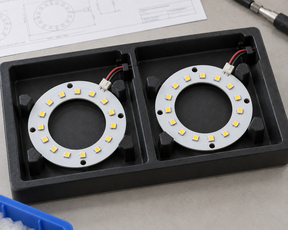
Specify the supplied format and the protection needed for board edges, components, optical parts and leads during shipment. Identify separately packed driver or control items and the documentation needed for assembly. Packaging and delivery arrangements follow the contents and destination stated in the quotation.
Resolve circuit and host responsibilities for the ring
After defining the ring geometry and lighting function, establish who supplies the control hardware and how the board connects to the host. A component order and a complete controlled assembly cover different work. Contact VST about any interface or operating behavior your LED ring PCB needs that the proposed design has not established; its outline alone cannot resolve those requirements.
Does a ring board come with a controller?+
VST can supply the driver, controller, software, protocol implementation and harness for the ring project. The quotation identifies which items are included, their required behavior and the remaining host integration work. A board-only order does not automatically include the complete control system.
Item
Scope to establish
Ring board
Circuit and connection function
Control hardware
Compatible output and channel behavior
Software
Host integration and responsibility
Can the opening serve as a cable passage instead of a lens aperture?+
That depends on the project. A cable passage changes the clearance and strain relief needed around the opening, which differs from an optical aperture. Keep the route clear of LEDs and fixings. Assess whether the protected passage belongs in the host or in the PCB itself.
Can a new LED ring PCB replace a visually similar ring?+
Evaluate both the mechanical and electrical interfaces first. Similar outlines can conceal different supply requirements, LED functions or connection assignments. Describe the original operating role when discussing a replacement with VST. Matching the outside diameter or LED count is not enough to establish that the new LED ring PCB is compatible.
Can VST supply a bare PCB instead of the assembled ring?+
Yes. VST can supply an LED ring PCB as a bare board, a populated LED board, a supported light engine or a complete assembly. Specify the format and the parts to include. A bare PCB order covers the agreed board fabrication; LED population, support, covers and control items belong in the quotation when required.