Horticulture LED module development for your grow light
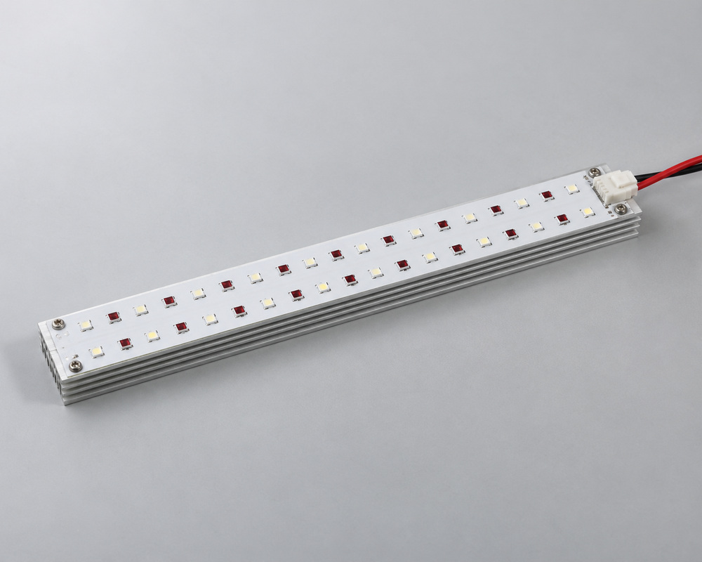
A horticulture LED module needs a compatible driver and a thermal path into the host luminaire. VST develops the source layout, circuit and mounting interfaces. The finished housing provides the environmental protection required for the growing area.
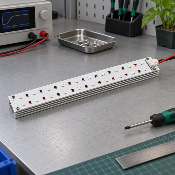
Source layout and thermal contact developed together
Board load matched to the proposed driver
Moisture protection specified for the finished luminaire
Describe the intended grow-light platform, approximate module envelope, and source objective; mention any choices that are still open.
Integrate the light engine into the luminaire
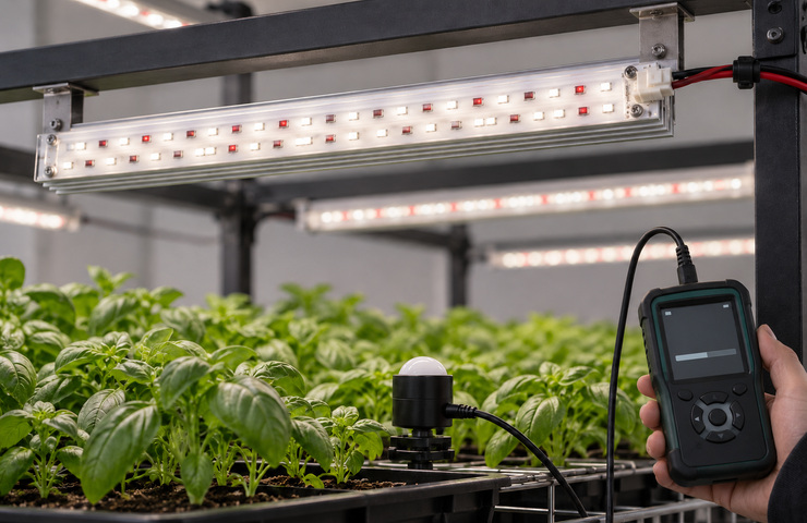
A horticulture LED module can suit several luminaire layouts. These concepts show protective housings for use near growing areas and irrigation. Host housings, crop racks, and crop-performance validation are separate from the module supply.
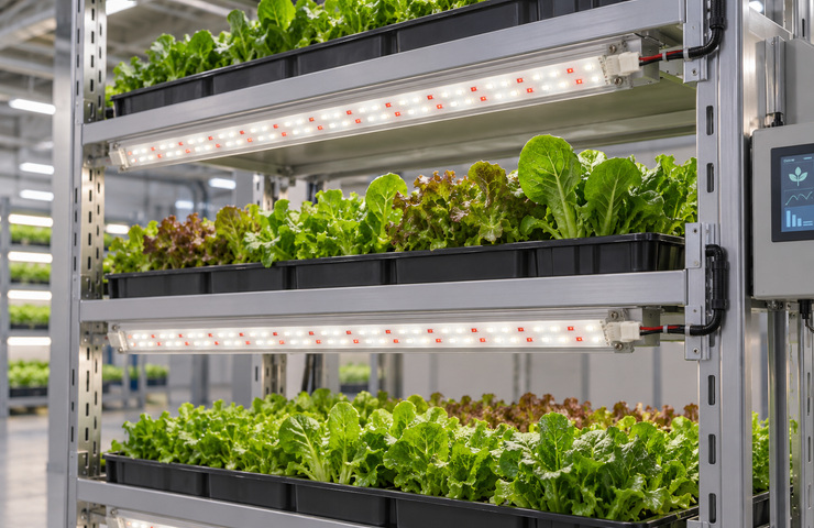
Multitier leafy-green rack
Operating environment
Closely spaced growing shelves with irrigation nearby
Buyer requirement
Provide a repeatable light-engine position above each crop tray.
Design constraint
Protection must separate electronics from the growing-zone environment.
Design direction
Enclose the board within a finished bar and route leads through a dry service channel.
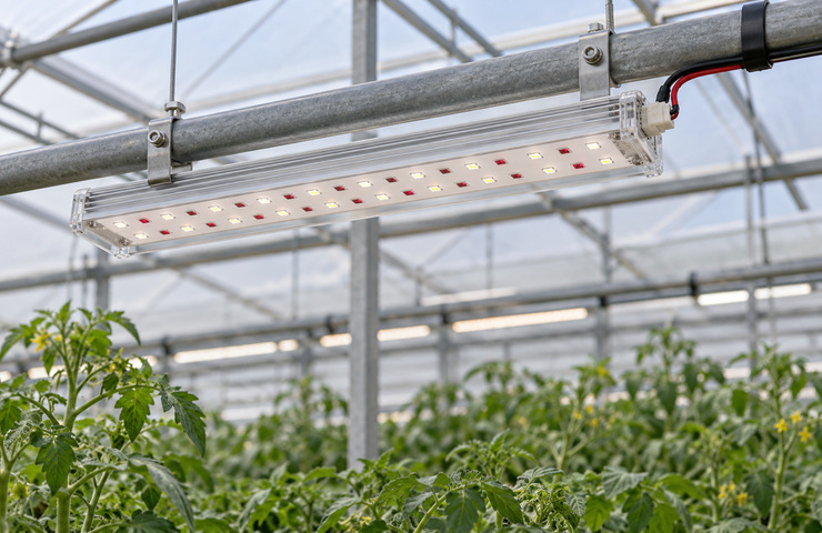
Greenhouse supplementary bar
Operating environment
Suspended luminaires above crop rows
Buyer requirement
Integrate modules into a supportable linear luminaire arrangement.
Design constraint
Host enclosure and support positions determine the assembly interface.
Design direction
Secure the light engine on its thermal support inside a protective housing.
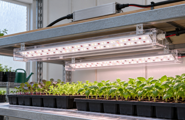
Propagation-bench luminaire
Operating environment
Seedling trays beneath a compact overhead frame
Buyer requirement
Build a serviceable source assembly for the selected propagation layout.
Design constraint
Driver location and cleaning access compete for available mounting space.
Design direction
Keep external drive equipment in a protected service zone.
Check the board, driver, and heat-transfer path
Emitter choice ignores the luminaire thermal path
Purchasing risk: A source that works briefly on a bench can operate differently in the finished housing.
Confirm: Host heat-spreading surface and cooling approach
VST solution direction: As your horticulture LED module manufacturer, VST develops the source arrangement with the heat-transfer path in the finished luminaire.
A matching board outline hides a different electrical load
Purchasing risk: Changing modules may exceed driver limits or alter channel behavior.
VST supports source layouts, board designs, wiring, and protection requirements as a horticulture LED module supplier. The proposal identifies how these parts connect to the host. Efficacy, lifetime, and yield figures need applicable measurement or validation.
Emitter mix and layout
For a horticulture LED module, provide the intended spectrum and source-performance targets: PPF (µmol/s) plus photon efficacy (µmol/J). Include the drive current, voltage, and temperature conditions for those targets. Emitter choice and placement can then be evaluated against electrical and thermal demands. Crop suitability requires separate evaluation in the growing system.
Buyer input: Channels that require independent current control
Board and thermal support
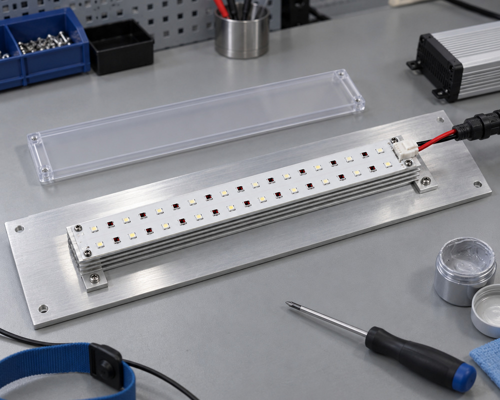
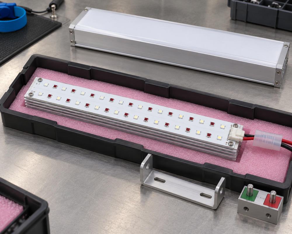
Board shape, fixings, and heat-spreader contact can be developed for the housing. A new arrangement may require PCB work or tooling. Mounting details must maintain thermal contact as well as physical fit.
Buyer input: Permitted mounting positions and available fixing access
Drive circuit and connection
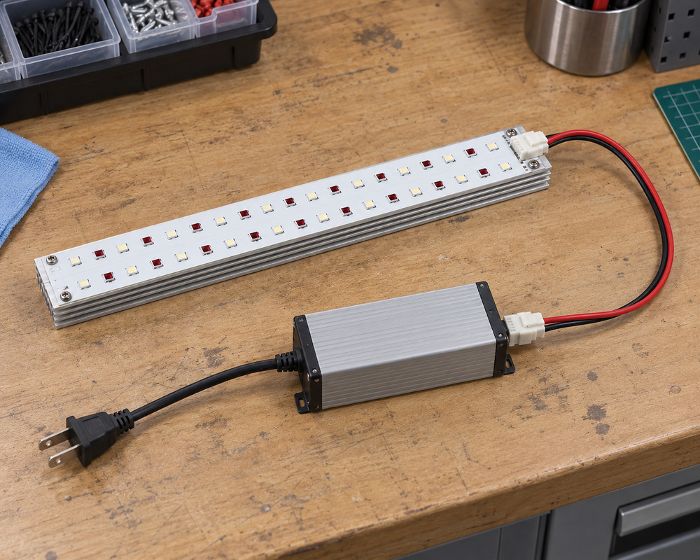
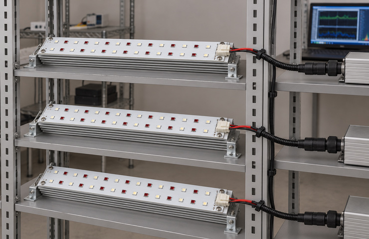
Series or parallel circuits, target current, and keyed leads can follow the driver design. These choices affect driver loading and fault behavior. Check them alongside the connector when assessing module interchangeability.
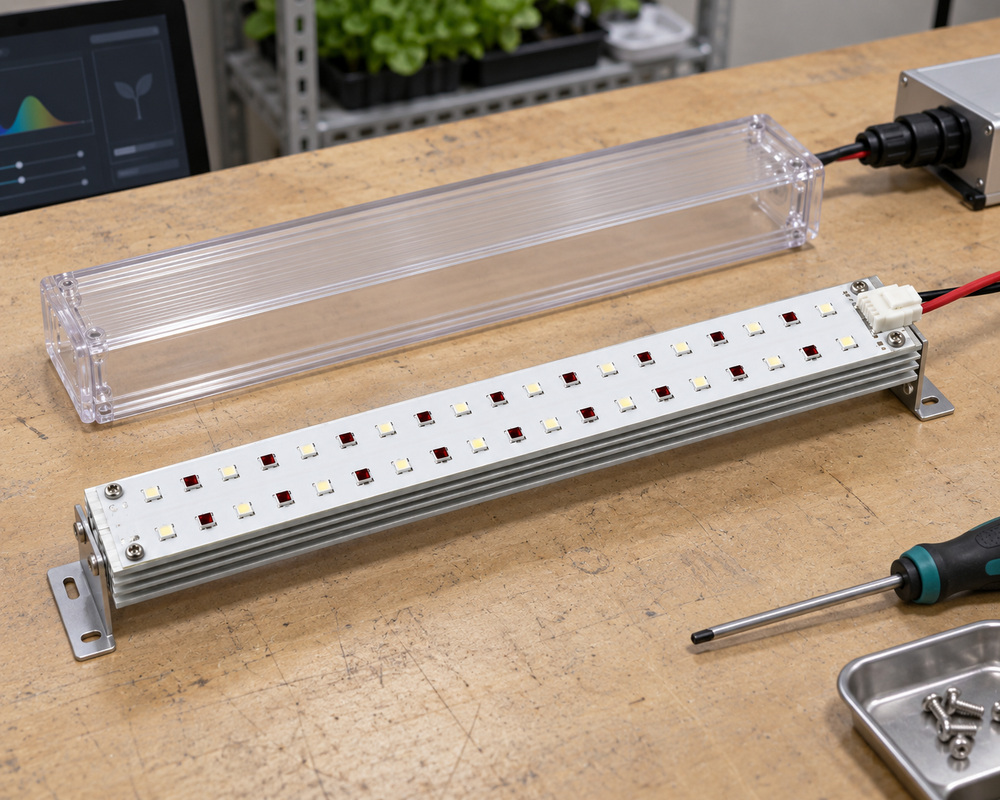
Evaluate board coatings or a protective housing for the intended environment. Protection choices affect service access and optical materials. An ingress rating requires applicable evidence for the assembly.
Buyer input: Host cleaning exposure and protection responsibility
Choose according to who develops the protective luminaire. A board leaves the housing and heat-spreading arrangement with the host design. An enclosed assembly includes more mechanical work, with the driver connection specified separately.
Decision factor
Board-level light engine
Enclosed light assembly
Buyer guidance
Protection boundary
Host provides enclosure and exposure protection
Protective construction belongs to the ordered assembly
Choose according to who controls the finished luminaire environment.
Thermal responsibility
Board contact depends on your host heat spreader
Module and thermal support are developed together
Keep the operating condition linked to the actual heat-transfer path.
Integration freedom
More freedom for your optical and housing layout
Enclosure geometry constrains the host mounting space
Use board supply when the luminaire platform already defines those interfaces.
Service replacement
Access usually requires opening the host housing
Assembly may be removed as one enclosed unit
Plan replacement around the service boundary of the finished grow light.
Coordinate the source, driver and housing, then record the accepted sample and production configuration before applying it to another luminaire version.
01
Specify the supplied assembly
Customer input: Chosen board or enclosed-assembly scope
VST work: Identify the thermal, optical, electrical, and protective connections between the ordered light engine and the host.
Stage output: A module proposal identifying luminaire integration responsibilities.
02
Build the thermal interface
Customer input: Heat-spreader drawing, contact area, and temperature limits (°C)
VST work: Develop the fixings and board contact on a representative heat spreader for the proposed module.
Stage output: A mechanical sample showing board contact with the thermal support.
03
Integrate the electrical pair
Customer input: Driver voltage/current range and the module wiring diagram
VST work: Connect the proposed board circuit and plug to its driver for functional sampling.
Stage output: A connected sample with specified drive conditions and wiring.
04
Define repeat assembly
Customer input: Selected construction and controlled component choices
VST work: Record the board design and inspection points for thermal contact, connections, and emitter selection.
Stage output: Assembly details and component controls for the released module version.
A horticulture LED module needs checks of spectrum, thermal contact, electrical load, installed coverage, and behavior over time. The methods below describe evaluation for the proposed assembly. Numerical results and biological outcomes need records from the actual project.
Source spectral characterization
Purpose: Identify the optical properties of the selected emitter configuration.
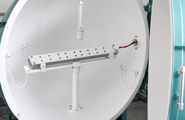
Method: Use appropriate spectral measurement and a suitable integrating-sphere setup for the sample.
Acceptance criteria: Measured spectral distribution, PPF (µmol/s), and photon efficacy (µmol/J) meet the project limits at the specified current, voltage, temperature measurement point, and optical measurement setup.
Evidence: Any spectral record must identify the actual module configuration.
Thermal-interface evaluation
Purpose: Assess whether heat leaves the board through the intended support.
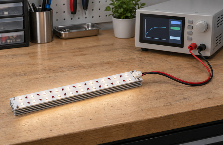
Method: Operate the module on the selected heat sink and measure relevant contact temperatures with suitable probes.
Acceptance criteria: Board and component thermal conditions remain within the defined design limits.
Evidence: Thermal findings apply to the mounting, drive conditions, and environment tested.
Drive current and electrical load
Purpose: Check compatibility between the module circuit and its proposed driver.
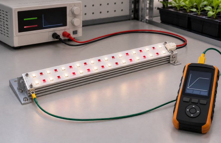
Method: Evaluate the connected light engine using appropriate regulated supply and electrical measurement equipment.
Acceptance criteria: The module load stays within the selected driver's operating definition.
Evidence: Electrical findings apply to the driver and module combination tested.
Installed canopy coverage
Purpose: Assess the assembled luminaire at its intended growing-plane geometry.
Method: Map the relevant plane with a suitable quantum sensor and record the measurement positions.
Acceptance criteria: The installed light arrangement meets the project's defined spatial photon targets.
Evidence: Canopy coverage needs project measurements of the installed arrangement.
Endurance observation
Purpose: Observe changes during the specified operating period.
Method: Run the secured modules under defined electrical and mounting conditions and inspect behavior over the chosen period.
Acceptance criteria: Assess observed changes against the agreed endurance criteria.
Evidence: Duration and any resulting record depend on the actual evaluation scope.
Module and luminaire measurement documents
Document the module design and identify the installed-luminaire measurements needed for the grow-light project.
Module circuit and construction specification
Project Specific
Record the source selection, connections, and board-to-support contact for the module version.
Optical evaluation scope
Project Specific
Specify separate tasks for source measurement and installed canopy photon measurements.
Discussing thermal contact brought our board and housing teams together. We could identify which details belonged to the module and which depended on our heat spreader.
For planning, general module guidance gives a 500-unit starting MOQ for light customization and 1,000 units for high customization, per model. Confirm applicability to the grow-light engine. The quotation sets the final quantity and design after the board, thermal support, source layout, and required development are established.
Sampling support
Light-engine samples can involve processing fees plus mold or tooling costs for new boards, fixtures, or parts. Confirm the applicable charges for the luminaire program. Any return of eligible sample spending or credit toward later bulk orders must state the amount, qualifying order, and settlement method in the written quotation or order terms.
Lead-time factors
General schedules use working-day ranges of 15 to 25 for lightly customized samples and 20 to 30 for their bulk production. For high customization, samples normally take 30 to 50 and bulk production 25 to 35. The quotation must set the light-engine schedule and separate time for optical or endurance evaluation. Work is timed after technical information is complete and applicable sampling charges, tooling charges, deposits, and remaining order conditions are fulfilled. Key-material reservation may shorten repeat work. Delivery is not guaranteed.
Tooling / NRE
Dedicated heat-transfer parts, boards, assembly tools, or optics may require tooling or NRE spending. Decide the recovery terms for the light-engine program before commissioning the work. Where eligible mold or tooling expenditure can be credited toward a later production payment, record the sum, qualifying order, and method of application.
Supply stability
Stable luminaire programs can use agreed forecasts to prepare emitters, boards, connectors, and other key materials, or reserve them for later orders. VST coordinates established suppliers and repeat-assembly checks for the released light engine. Configuration changes need to be recorded. Finished stock is not guaranteed for every spectrum or housing design.
Packaging & logistics
Use custom packing to protect emitters, board edges, and plugs before luminaire assembly. Branding can include artwork, carton marks, labels, and barcodes. Manuals and instruction sheets can be adapted to the module version ordered. Coordinate dispatch within the agreement; freight, packing counts, destination charges, and transit duration depend on the actual route and order.
The horticulture LED module is one part of the installed growing system. These questions address driver selection, measurement levels, warranties, and crop claims. If you need to reuse a module across platforms or have another unresolved requirement, discuss that issue with VST before specifying the supply and evaluation work.
Can I discuss a horticulture LED module before selecting the driver?+
Yes. The initial discussion can identify the module requirements while the driver choice remains open. Mark provisional electrical assumptions in the proposal. Finalize the load specification only when the driver and board circuit have been matched.
Which performance figure belongs to which assembly?+
Compare performance figures measured at the same assembly level and conditions.
Boundary
What it describes
LED package
The individual component at stated conditions
Module
The assembled light engine and drive state
Installed luminaire
The full assembly and growing-plane arrangement
Can an LED-package lifetime value become the module warranty?+
The warranty comes from the order terms. Lifetime evidence needs to apply to the module design and operating conditions, including its driver, heat-transfer path, and assembly. A lifetime figure for an individual emitter cannot by itself establish the module warranty.
Can a spectral change guarantee a higher crop yield?+
Crop response depends on species, growth stage, environment, and operating protocol as well as spectrum. Evaluate the proposed sources in the growing system and support any yield claim with appropriate experiments. A spectral change alone provides no yield guarantee.
What source specifications are needed for a horticulture LED module?+
Use project targets or data for the actual sample. Include the operating and measurement conditions with every performance figure.
Specification
Information to provide
Spectrum
Spectral-distribution file or required source bands (nm)
Photon output
PPF (µmol/s) and the spectral range and optical setup used to measure it
Photon efficacy
µmol/J, with the electrical input boundary and measurement conditions
Electrical drive
Operating current (mA or A), voltage (V), channel assignments, and pinout
Thermal interface
Host contact design, temperature limits (°C), measurement point, and test temperature
Mechanical fit
Board dimensions, fixing positions, connector space, and tolerances in mm