Custom Growth Chamber LED Lighting for OEM Research Equipment
VST Lighting develops custom growth chamber LED lighting assemblies for laboratory equipment manufacturers, plant research facilities and controlled-environment system suppliers. Our OEM lighting solutions can be designed around chamber dimensions, LED spectrum, canopy-lighting requirements, mounting arrangements and controller interfaces.
From reach-in research chambers to multilayer propagation cabinets and walk-in growth rooms, VST supports LED module customization, prototype development and electrical integration. Photosynthetic photon flux density (PPFD), spectral performance and lighting uniformity must be evaluated under the intended chamber conditions.
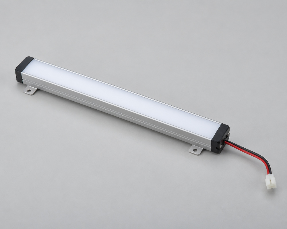
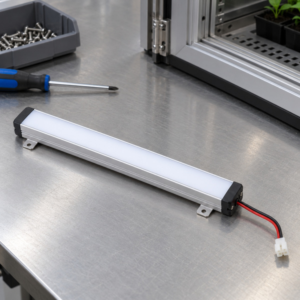
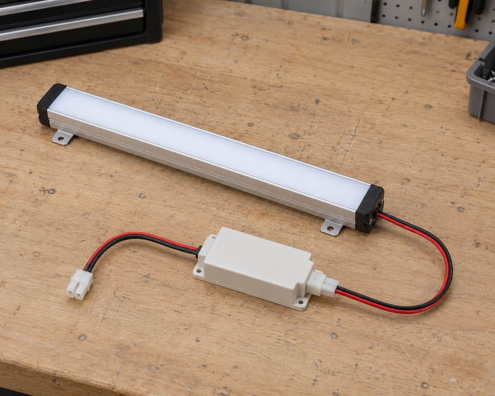
Custom LED grow light bars and modules for research chamber integration
Project-specific spectral configurations, mounting dimensions and controller connections
OEM sampling and optical evaluation to support repeatable lighting assembly production
Share your chamber dimensions, research application, required spectrum, target canopy PPFD and control specifications for an engineering review.
LED Growth Chamber Lighting for Different Research Environments
LED growth chamber lighting must match the available growing area, shelf arrangement and intended plant-canopy position. Reach-in chambers, multilayer propagation cabinets and walk-in research rooms may require different light-bar dimensions, spectral configurations and mounting layouts. VST develops custom LED assemblies around these mechanical and electrical requirements, while canopy photon measurements and biological validation remain specific to the chamber and research protocol.
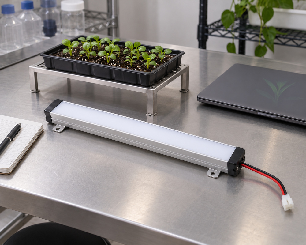
LED Lighting for Reach-In Growth Chambers
Operating environment
Individual plants beneath a chamber ceiling
Buyer requirement
Provide a defined growing plane for the chosen research arrangement.
Design constraint
Plant height changes the source-to-canopy distance.
Design direction
Mount enclosed bars above the usable zone and preserve clearance for canopy adjustment.
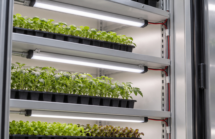
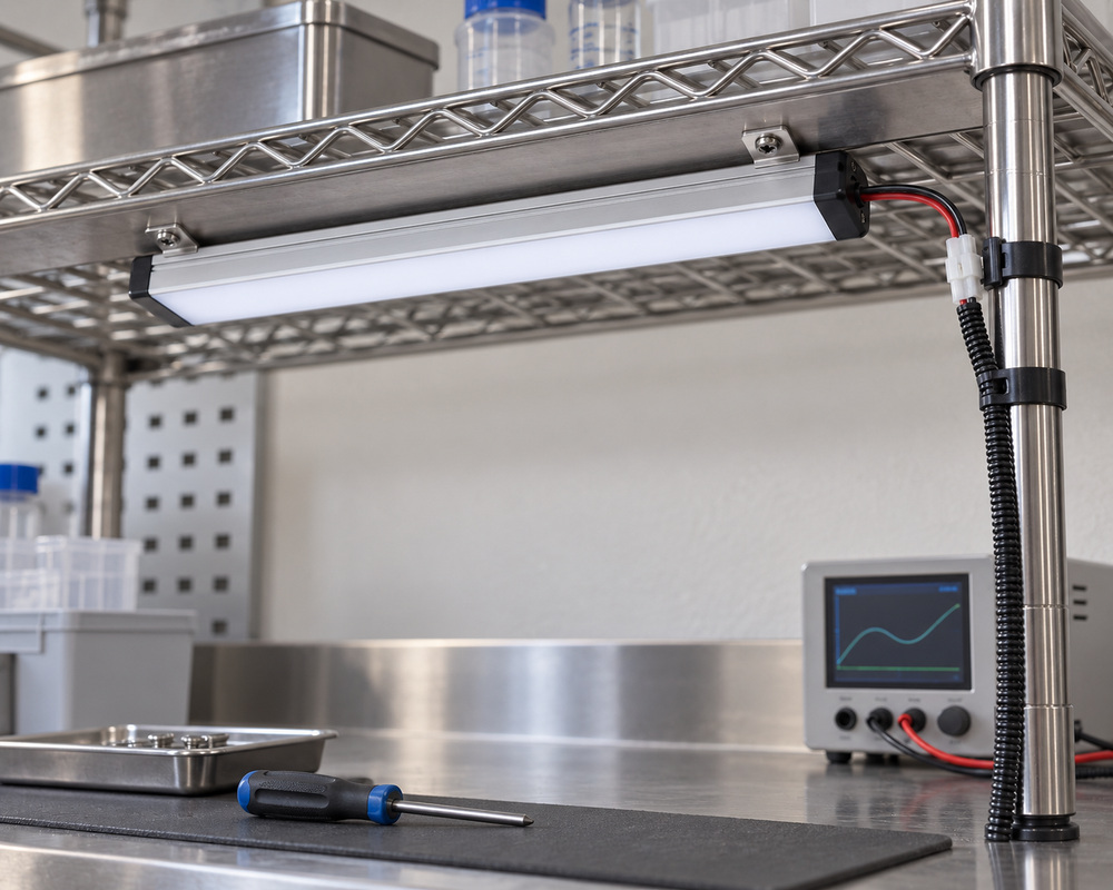
Multilayer Plant Growth Chamber LED Lighting
Operating environment
Seedling trays on closely spaced shelves
Buyer requirement
Use each shelf as a distinct controlled growing area.
Design constraint
Low headroom makes cables and protective covers part of the mounting envelope.
Design direction
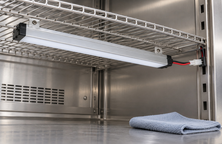
Place enclosed bars under the upper shelf with protected side-channel wiring.
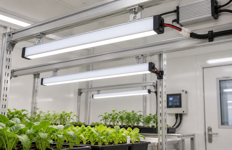
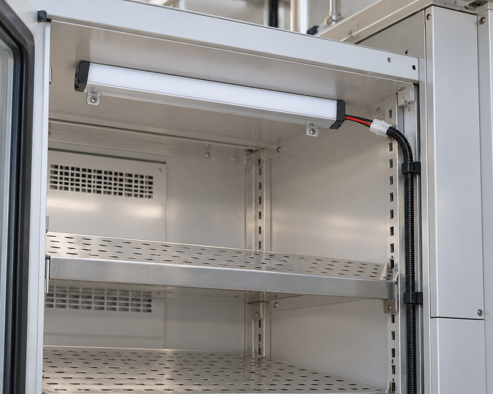
Walk-in plant research room
Operating environment
Larger research plots below support rails
Buyer requirement
Arrange lighting around the research zones and access routes.
Design constraint
Room geometry and support positions affect the achievable layout.
Design direction
Develop a modular bar arrangement while keeping service hardware above the working area.
Avoid Common Growth Chamber LED Lighting Problems
A lumen rating is used as the canopy-light target
Purchasing risk: The proposed source may look bright yet fail to describe plant-relevant photon conditions.
Confirm: Required photon metric and measurement plane
VST solution direction: Define the plant-relevant photon targets and the measurements needed to assess them.
Changing shelf height changes the experiment
Purchasing risk: A different canopy distance can change spatial exposure without an electrical change.
Confirm: Allowed canopy-height adjustments during the protocol
VST solution direction: Record mounting positions and canopy measurement height as controlled experimental conditions.
The control system cannot reproduce the intended schedule
Purchasing risk: Unspecified channel behavior can make nominally identical runs differ.
Confirm: Required schedule and channel independence
VST solution direction: Specify the required channel and schedule behavior, then check whether the proposed dimmer can reproduce it.
VST supports growth chamber LED module customization across spectral configuration, mechanical dimensions, electrical connections and environmental protection requirements. Depending on the research protocol, the proposed assembly may include fixed-spectrum or independently controlled LED channels, custom light-bar lengths, mounting brackets, compatible drivers and protected connectors. The agreed specification should distinguish source-level performance from canopy measurements and complete-chamber validation.
Spectral configuration
The spectral power distribution (SPD) of a growth chamber LED light describes its optical output across wavelengths. VST can evaluate broad-spectrum configurations or project-specific combinations of white, red, blue and far-red LEDs where applicable. Buyers should specify required wavelength bands, channel independence and relevant source measurements. Photosynthetic photon flux (PPF), expressed in µmol/s, may be used as a source-level metric, while canopy PPFD and plant response require separate assessment.
Buyer input: Target spectrum for the intended research condition
Light placement and spacing
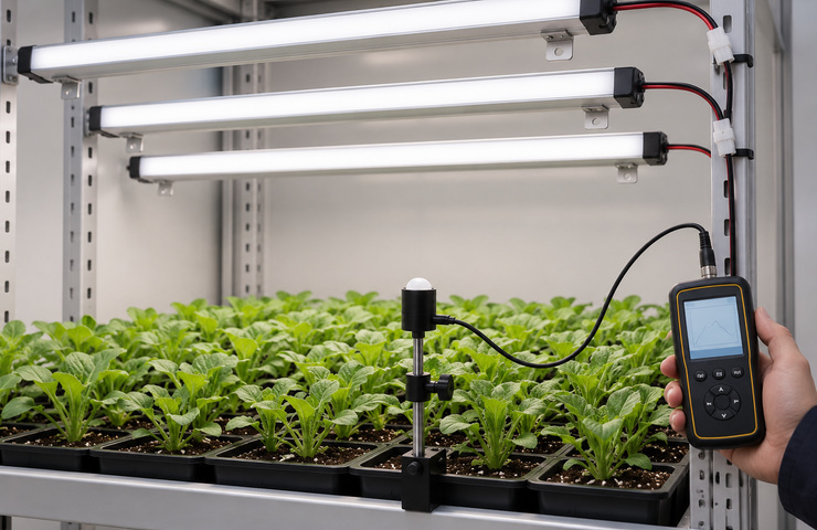
LED grow light bar length, spacing and mounting height influence photon distribution across the usable growing area. VST can evaluate custom bar dimensions, fixing arrangements and cable routes for reach-in chambers and multilayer shelves. Canopy PPFD mapping should be performed at the specified measurement plane and operating state. Uniformity results must identify the measurement grid, light-to-canopy distance and calculation method.
Growth chamber LED lighting may require dimming, timed photoperiod operation or independent spectral-channel control. VST reviews driver compatibility, electrical supply, dimming signals and channel assignments against the chamber's existing controller. Daily light integral (DLI) may be defined by the research protocol using measured PPFD and the lighting schedule. Reproducibility depends on recording the actual operating states rather than assuming identical settings produce identical canopy exposure.
Buyer input: Controller output type and behavior at minimum output
Protection and cleaning access
Plant growth chambers may expose LED lighting assemblies to humidity, condensation and cleaning procedures. VST can evaluate protective covers, connector placement, cable routing and accessible mounting arrangements according to the specified operating environment. Material compatibility, ingress protection and chemical resistance require appropriate evidence for the selected construction. Maintenance access should be verified without obstructing shelves, trays or chamber airflow.
Buyer input: Cleaning method and expected condensation exposure
Fixed-Spectrum vs. Multi-Channel Growth Chamber LED Lighting
Fixed-spectrum LED growth chamber lighting can suit research protocols that require a stable spectral configuration and adjustable overall output. Independently controlled spectral channels provide additional flexibility when wavelength composition is an experimental variable. However, multichannel systems require compatible drivers, controller interfaces and documented operating states. VST evaluates the appropriate design according to the research protocol, electrical system and required measurement reproducibility.
Decision factor
Fixed-spectrum assembly
Independent spectral channels
Buyer guidance
Experimental flexibility
One source spectrum with overall output adjustment
Selected channels change the spectral composition
Use independent channels when spectral composition is an experimental variable.
Control integration
A single defined dimming interface
Multiple channel assignments and control states
Check the chamber controller before selecting a multichannel assembly.
Reproducibility burden
Record intensity state and mounting conditions
Record each channel state as well as geometry
Choose the architecture your protocol can document consistently.
Electrical complexity
Simpler driver and wiring relationship
More driver outputs and channel connections
Allow service space for the actual channel architecture.
OEM Growth Chamber LED Lighting Development and Prototyping
VST supports custom growth chamber lighting development from initial research requirements through LED assembly design, mounting evaluation, controller integration and production documentation. The process defines the intended spectrum, growing area, source placement and electrical interfaces before sample evaluation. Project-specific measurements are then used to assess the proposed lighting arrangement, while complete-chamber performance and biological research outcomes require separate validation.
01
Specify the optical requirements
Customer input: Selected experimental variables
VST work: Identify the source characteristics needed in the lighting specification and distinguish them from canopy and biological objectives.
Stage output: Lighting requirements tied to measurable experimental conditions.
02
Prepare the shelf layout
Customer input: Shelf layout and allowed canopy-height adjustments (mm)
VST work: Develop light mounting and cable routes in a representative shelf, with clearance for the planned growing plane.
Stage output: A shelf layout with accessible lights and cable connections.
03
Integrate the control
Customer input: Controller outputs, channel assignments, and photoperiod (h/day)
VST work: Connect the proposed driver and assign channels for the chamber controller and required lighting functions.
Stage output: A functional sample with specified control states.
04
Record the chamber installation
Customer input: Chosen configuration and operating-state records
VST work: Record installation details, repeat-production checks, and the operating conditions needed for subsequent chamber evaluation.
Stage output: Assembly and connection details for the chamber equipment.
Growth Chamber LED Lighting Testing and PPFD Evaluation
Growth chamber LED lighting evaluation should distinguish source spectral measurements from photon exposure at the plant canopy. Depending on the project, optical assessment may include spectral power distribution, photosynthetic photon flux and canopy PPFD mapping using suitable instruments. Additional checks can address LED assembly temperature, photoperiod operation, dimming response, mounting fit and maintenance access. Measurement results must identify the tested assembly, operating state, measurement distance and applicable acceptance criteria. Plant-growth outcomes require separate biological evaluation.
Canopy PPFD mapping
Purpose: Evaluate spatial photon exposure across the intended growing plane.
Method: Arrange suitable quantum-sensor measurements at defined grid positions under the installed assembly.
Acceptance criteria: Measured canopy PPFD (µmol/m²/s), the project-defined uniformity calculation and limit, measurement height, and grid meet the protocol requirements at the stated control settings.
Evidence: PPFD mapping is project-specific; no measured map is supplied with this concept.
Source spectral assessment
Purpose: Measure the spectrum of the proposed light source.
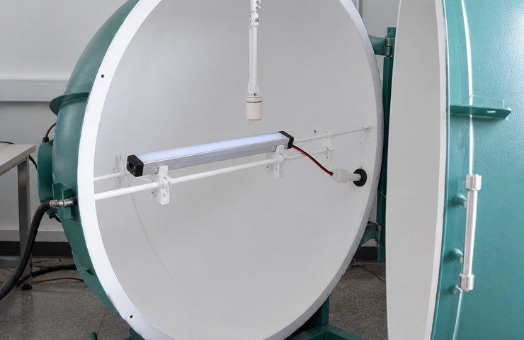
Method: Use suitable spectral instruments and an integrating-sphere setup appropriate to the source and measurement configuration.
Acceptance criteria: Measured source characteristics correspond to the requested spectral configuration.
Evidence: Any spectral result must identify the sample and measurement setup.
Assembly surface-temperature check
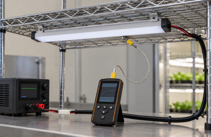
Purpose: Screen fixture and mounting-interface temperatures under the defined chamber operating conditions.
Method: Measure contact temperatures at the identified fixture and mounting-interface points under the defined chamber operating and installation conditions.
Acceptance criteria: Recorded temperatures meet the limits assigned to the identified measurement points and mounting conditions.
Evidence: Temperature regulation of the complete chamber needs separate system evaluation.
Photoperiod and dimming behavior
Purpose: Check whether the electrical interface reproduces the selected control state.
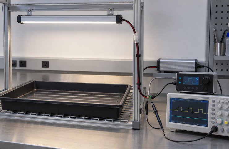
Method: Check timed operation, channel states, and low-output behavior with suitable control and measurement equipment.
Acceptance criteria: Lighting follows the specified schedule and interface without unintended state changes.
Evidence: Controller findings apply to the tested assembly and program configuration.
Shelf fit and cleaning access
Purpose: Check access for installation and maintenance in the growing area.
Method: Inspect the unpowered assembly, fixing access, and protected cable path within a representative shelf arrangement.
Acceptance criteria: The light can be serviced without obstructing the agreed tray and cleaning access.
Evidence: Chemical resistance requires evidence in addition to the mechanical access check.
Optical and control records
Record source specifications and canopy measurements against their respective assemblies and operating states.
Optical and canopy-assessment scope
Project Specific
Document the light-source parameters and canopy measurement positions separately for the chamber.
Control interface definition
Project Specific
Specify the channel assignments, operating states, and host-controller connections for the proposed lights.
Separating the source target from canopy measurements helped us describe the research conditions. We could see why one source rating would not describe every shelf position.
Research Equipment CompanyR&D Engineer · Canada
Source and canopy specification separation
The control discussion started with the states we needed to reproduce. It helped us decide whether the existing chamber controller suited the proposed lights.
The mounting proposal showed how the trays would pass the lights and how the cables would be protected. That made shelf access easier to discuss with our equipment team.
Laboratory Equipment CompanyProduct Manager · United States
The general starting MOQ is 500 units per model for light customization or 1,000 for high customization. Confirm whether these quantities apply to the chamber-lighting design before ordering. A new board, channel arrangement, optical part, or mounting fixture can change the development work and the quantity set in the project quotation.
Sampling support
Chamber-light sample processing and any new molds or tooling require charges agreed for the project. Eligibility for returning sample costs or applying them to later production remains subject to written conditions. Specify the eligible amount, qualifying order, and repayment or credit method before committing to sample development.
Lead-time factors
General planning allows 15 to 25 working days for light samples, 20 to 30 for light production, 30 to 50 for high-customization samples, and 25 to 35 for high-customization production. Verify applicability to the chamber assembly and schedule research-specific evaluation separately. Start timing only after complete technical information and fulfillment of applicable sampling and tooling payments, deposits, and remaining order conditions. Material reservations for stable demand may reduce later schedules. Shipment dates require a separate agreement.
Tooling / NRE
Chamber optics, source boards, profiles, and fixtures may create tooling or NRE charges. Confirm whether mold or tooling costs qualify for a credit on a future production order. The commercial terms must identify that order, the amount eligible for credit, and how it reduces payment. General guidance does not establish project-specific recovery.
Supply stability
For stable chamber-lighting programs, VST can coordinate agreed source-material forecasts and production checks for the accepted assembly. Record changes to spectral channels, wiring, or mountings before repeat orders. Material reservation and finished-assembly availability need separate agreements for the actual order.
Packaging & logistics
Packing should protect light covers and cable ends through equipment assembly. Custom options include product packaging, carton marks, brand artwork, labels, and barcodes. User manuals and instruction sheets can match the ordered version. Shipment coordination follows the agreement. Carton sizes, packing quantities, transit duration, and freight cost depend on the shipment plan.
A source change can affect an experiment even when the new light fits the same mounting position. These questions explain how to assess a growth chamber light for replacement or reuse. Discuss any unresolved equivalence requirement for your growth chamber lighting with VST so the relevant measurements and equipment responsibilities can be identified.
Can a growth chamber light replace fluorescent lighting without changing the protocol?+
A retrofit needs assessment of spectrum, spatial exposure, heat, and the operating state recorded in the protocol. Fit and power consumption provide only part of the comparison. Use the relevant measurements and research-system assessment to determine whether the change preserves the required experimental conditions and biological response.
Which lighting claim needs which evidence?+
For growth chamber lighting, each claim needs evidence at the relevant measurement level.
Claim
Relevant evidence
Source spectrum
Sample-specific spectral measurement
Canopy exposure
Measurements at the specified growing plane
Plant response
Applicable biological experiment
Can the same light assembly serve every crop or experiment?+
An assembly may be reused when its optical, control, and environmental conditions suit the new protocol. Species, growth stages, and research questions can require different conditions. Evaluate reuse against those requirements before applying one spectrum across experiments.
Can a spare light restore the original experimental conditions?+
Record the original assembly design and operating state, then assess any change to the source or connections against the protocol. A matching outline is only a fit check. Replacement planning for growth chamber lighting needs to identify the measurements that establish equivalence for the chamber and experiment.
Which specifications should I provide for growth chamber lighting?+
Fill the optical and control requirements from your research protocol. Keep source specifications, canopy measurements, and biological objectives separate.
Specification
Information to provide
Spectrum
Spectral distribution or required channels and wavelength bands (nm)
Canopy PPFD
Target and limits in µmol/m²/s at the specified operating state
Measurement layout
Canopy plane, source distance and grid spacing (mm), usable area, and sensor suitability
Uniformity
Required calculation, such as minimum/mean PPFD, its limit, and the evaluation area
Photoperiod and control
Light/dark schedule (h/day), channel assignments, dimming signals, and allowed state changes