Custom Embedded LED Lighting for OEM Product Integration
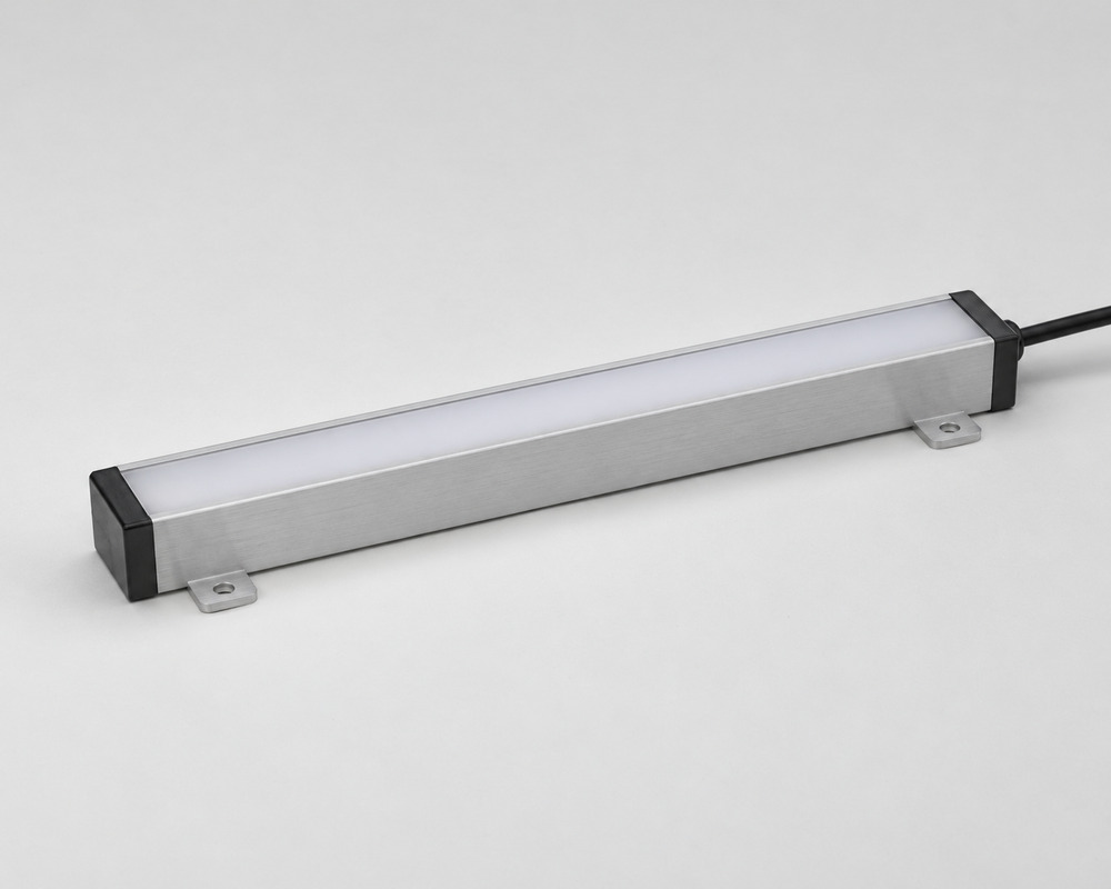
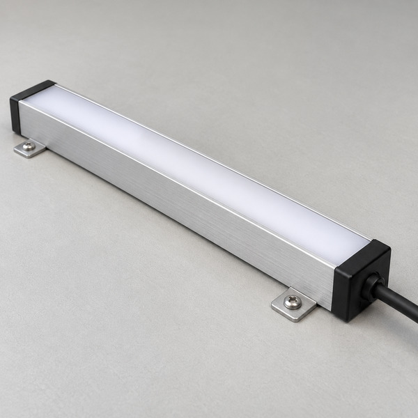
VST Lighting develops custom embedded LED lighting for equipment manufacturers, furniture brands and display-system suppliers. Our OEM LED lighting solutions combine compact light engines, aluminum profiles, diffusers and customized wiring to fit your product's mounting space, electrical system and lighting requirements.
From recessed LED modules to low-profile lighting bars, we support product-specific dimensions, light distribution, thermal management and sample verification before bulk production.
Embedded LED modules customized for equipment, cabinets and display enclosures
Lighting design coordinated with mounting, wiring, thermal and optical requirements
OEM/ODM sample development and controlled repeat production
Share your product drawing, installation dimensions or reference photo to begin an engineering review.
Match the light assembly to its working space
Embedded LED lighting integrates illumination directly into equipment housings, furniture cavities and display structures. Unlike standalone fixtures, custom LED modules must match the available installation depth, mounting points, wiring route and service access. VST evaluates these conditions alongside brightness, glare control and heat dissipation to help OEM buyers select a practical lighting assembly.
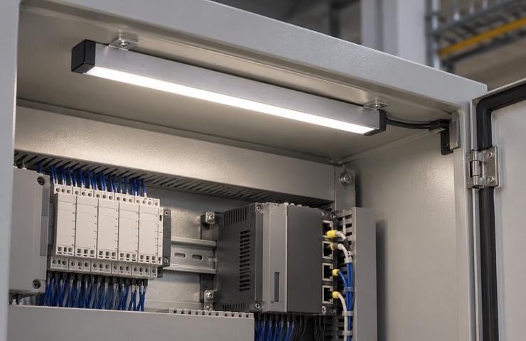
Equipment service compartment
Operating environment
Enclosed indoor machine space with routine service access.
Buyer requirement
Make connectors and service points visible when the access door opens.
Design constraint
Moving panels can trap a cable or obscure the luminous face.
Design direction
A shielded recessed bar can sit clear of the moving door.
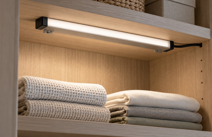
Furniture storage recess
Operating environment
An indoor furniture cavity with a limited rear wiring channel.
Buyer requirement
Light the stored contents without exposing the source in the normal viewing position.
Design constraint
The usable depth must include the cover and mounting hardware.
Design direction
A shallow finished profile can fit the recess and leave the shelf space usable.
Display-system access bay
Operating environment
A glazed indoor equipment enclosure viewed from several standing positions.
Buyer requirement
Illuminate the working area without a bright reflection across the front glazing.
Design constraint
Glass and trim change the sightlines seen at the workbench.
Design direction
Position a covered source behind the enclosure trim with serviceable cable routing.
Catch integration failures before host assembly
Connector accessible only before assembly
Purchasing risk: A service replacement can require dismantling unrelated host parts.
Confirm: Final service opening and connector reach
VST solution direction: Locate the detachable connection on the accessible side of the finished enclosure.
Host wall used as an uncertain heat path
Purchasing risk: An isolated working sample can behave differently inside the closed product.
Confirm: Host-wall material and contact surface
VST solution direction: Evaluate heat transfer through the intended support surface, including how it differs from free-air operation.
Different teams own overlapping interfaces
Purchasing risk: The host harness and lighting lead may arrive with incompatible endpoints.
Confirm: Harness responsibility at the mating connector
VST solution direction: List the light engine, mating parts and host wiring separately in the quotation.
Choose the interfaces your embedded assembly needs
VST develops custom embedded LED modules around your product’s mechanical, optical, electrical and thermal requirements. Depending on the project, customization may include module dimensions, LED PCB layout, diffuser type, input voltage, wiring length, connector position and mounting hardware. An existing platform may be adapted for simpler requirements, while a new profile or board design may require dedicated development.
Mounting envelope
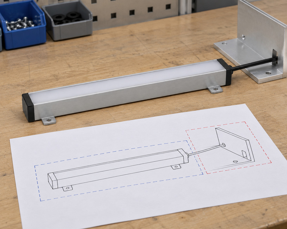
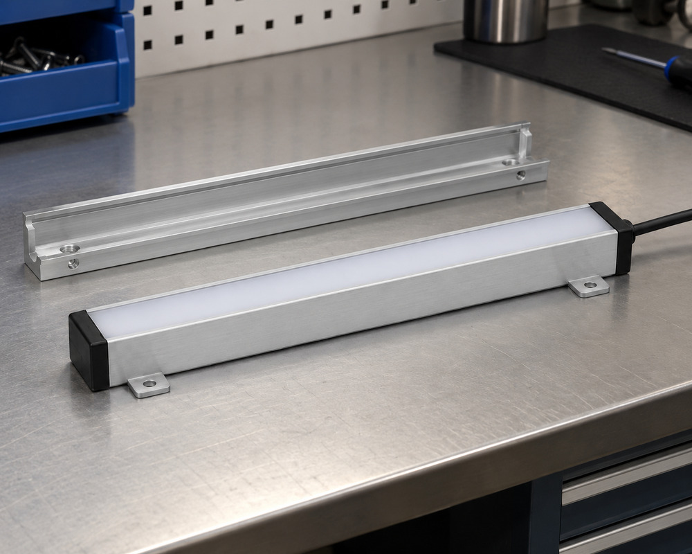
The embedded LED module must fit the available recess, including the aluminum profile, diffuser, mounting clips, cable exit and fixing clearance. Custom dimensions should be checked against the finished product, not only the empty installation opening. VST can review low-profile construction and mounting arrangements for space-constrained OEM assemblies.
Buyer input: Permitted projection beyond the finished host surface
Visible light and shielding
LED placement, diffuser material and profile depth influence light uniformity, glare and visible LED points. Depending on the lighting task, VST can evaluate brightness, color temperature (CCT), color rendering (CRI) and light distribution. The selected optical design should be checked from the normal viewing positions with the diffuser installed.
Buyer input: Normal viewing positions around the product
Electrical boundary
Input voltage, power consumption, driver compatibility and wiring connections must match the host product's electrical system. VST reviews cable length, connector type, polarity, wiring harness routing and the boundary between the LED module and separately supplied power equipment. Any dimming or control requirements should be identified before sampling.
Buyer input: Available supply type and isolation boundary
Thermal support
Embedded LED lighting installed inside enclosed equipment requires a defined heat-dissipation path. The LED PCB, aluminum carrier, mounting surface and surrounding materials influence operating temperature. VST evaluates thermal contact and support conditions using the intended assembly arrangement, helping identify overheating risks before production approval.
Buyer input: Allowed contact area on the host chassis
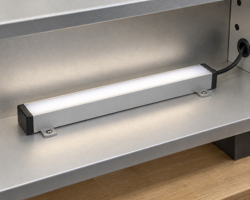
Choosing between a recessed LED lighting module and a surface-mounted LED bar depends on installation depth, visibility, wiring access and future maintenance. Recessed modules provide a more concealed appearance when sufficient cavity space is available, while surface-mounted designs can simplify fixing and service access. VST evaluates both constructions against your product’s mechanical and electrical requirements before confirming a sample design.
Decision factor
Recessed covered engine
Surface-mounted covered bar
Buyer guidance
Host preparation
Needs a suitable recess and rear clearance
Uses an accessible fixing surface and visible profile
Choose around the host tooling already available to your product.
Service approach
Removal depends on access to the inset fixing
Fixings can be reachable from the illuminated compartment
Avoid a mounting position blocked by permanently assembled host parts.
Visual impact
Trim can conceal most of the profile
Housing remains visible within the host space
Decide whether the housing is a visible product detail.
Cable route
Rear or end access within the recess
Protected routing along the mounting surface
Include the cable turn before selecting the usable profile length.
Develop embedded LED lighting around the host interfaces
VST supports OEM embedded LED lighting development from initial drawings and mechanical review through prototype evaluation and repeat-production preparation. Our engineering process coordinates the LED light engine, diffuser, mounting structure, power interface and wiring arrangement with the intended host product. Customers can evaluate samples in their own equipment or arrange a fit trial at VST using a representative host, with responsibilities agreed during quotation.
01
Define the assembly boundary
Customer input: Host photos or a structure sketch, available space, intended lighting task and supply interface.
VST work: VST identifies the profile, cover and connection interfaces and separates the quoted lighting parts from surrounding host items.
Stage output: A proposed parts boundary and mounting/interface sketch.
Open dimensions can be listed for resolution before sample layout.
02
Develop the representative build
Customer input: Mounting positions, fixing access, cable clearance, support contact and any existing sample.
VST work: VST develops the profile, board, cover and lead arrangement for the identified host revision.
Stage output: A representative light assembly with its connection and support details.
Prototype work starts from the agreed interfaces and supplied scope.
03
Evaluate host access
Customer input: Choose the trial route. For a VST trial, provide the representative host; for your trial, send installation photos and fit observations.
VST work: VST trials the sample in the host you provide or reviews your fit-trial feedback, then discusses changes to mounting access, cable clearance and serviceability.
Stage output: Agreed fit observations and proposed changes linked to the host and sample revisions.
The quotation identifies who performs the trial and which fit records will be delivered.
04
Establish repeat-build controls
Customer input: The accepted sample revision, resolved host changes and parts that must stay consistent.
VST work: VST carries the agreed mounting, connection and assembly revisions into the production definition.
Stage output: A build definition identifying part revisions and assembly checkpoints.
Changes to host interfaces are considered before the next build.
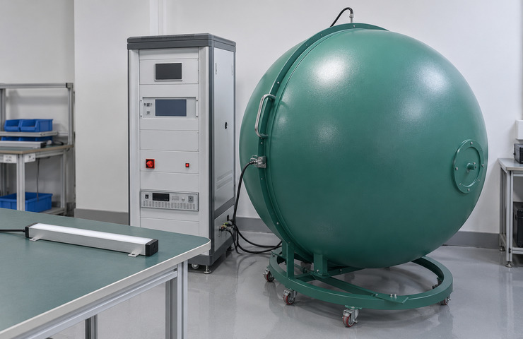
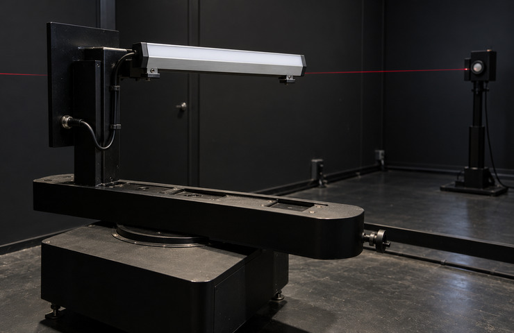
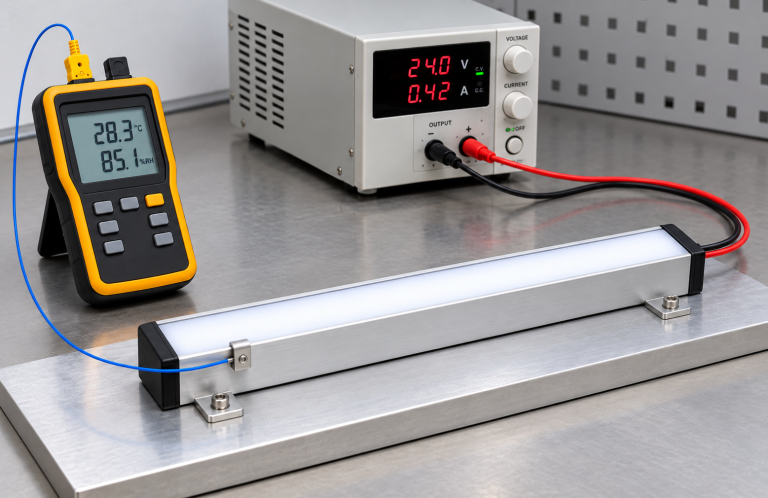
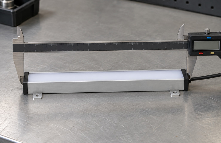
Reliable embedded LED lighting requires more than a functional LED board. VST evaluates the agreed sample against optical, mechanical, electrical and thermal requirements using suitable testing equipment. Depending on the approved test scope, measurements may cover luminous flux, color characteristics, light distribution, operating temperature, fixing dimensions and functional endurance. Results are linked to the tested assembly, operating conditions and sample revision to support informed OEM production decisions.
Luminous and color measurement
Purpose: Establish the light output and color of the selected covered assembly.
Method: Measure the powered assembly inside a closed integrating sphere using a suitable internal support.
Acceptance criteria: Specified luminous and color characteristics at the recorded electrical condition.
Evidence: Project-generated optical record only after the agreed measurement of the identified assembly and electrical condition.
Assembly light distribution
Purpose: Assess how the cover and shielding affect the assembly's angular light output before evaluating it in the equipment.
Method: Measure the assembly's angular light distribution with a suitable goniophotometer under recorded operating and mounting conditions.
Acceptance criteria: The intended angular coverage without obstructed measurement geometry.
Evidence: Project-generated distribution record only after the agreed assembly measurement; file delivery and format depend on the test scope.
Host-support thermal evaluation
Purpose: Check heat transfer from the light assembly to its selected support surface.
Method: Operate the mounted assembly and record temperature at defined housing and support contact points.
Acceptance criteria: Component and support temperature limits for the recorded mounting condition.
Evidence: A project thermal record is created only after the agreed evaluation, with the sample build and support contact identified.
Envelope and fixing inspection
Purpose: Find profile or mounting dimensions that prevent the intended host fit.
Method: Measure the assembly envelope with a caliper and inspect the location and access of its fixing features.
Acceptance criteria: Dimensions and fixing positions compatible with the selected host envelope.
Evidence: Project inspection notes follow the agreed dimensional and fixing checks on the identified revision.
Operating endurance evaluation
Purpose: Observe changes during extended operation of the chosen build.
Method: Operate the supported light engines with the agreed electrical settings and mounting, recording function and appearance during the defined test period.
Acceptance criteria: Stable function and acceptable visual condition against the development specification.
Evidence: A project operation record must state the actual conditions, duration and observations; it does not establish service life.
Document the host assembly interfaces
Assembly interface drawing
Project Specific
A project drawing can show the mounting envelope, cable exit and where the connection remains accessible.
Sample build and evaluation scope
Project Specific
The agreed evaluation scope identifies the sample construction and the host conditions to test.
A lightly customized model typically starts at 500 units; high customization normally starts at 1,000 units per model. Adapting a suitable lead or platform involves less development than a new host-specific structure. The quotation sets the final quantity once the mounting and electrical requirements are defined.
Sampling support
VST supports sample development, with processing charges. New production resources may also incur mold or tooling costs. Written project terms can provide for returning eligible sample expenditure or crediting it toward a later production payment. The quotation specifies the amount and how the credit applies.
Lead-time factors
Light-customization samples normally take 15-25 working days, with bulk production at 20-30. For high customization, allow 30-50 working days for samples and 25-35 for production. Timing starts once the necessary technical information and applicable fees, tooling payments or deposit conditions are complete. Stable demand may support key-material reservation and shorter repeat schedules. These are planning ranges, not fixed delivery guarantees.
Tooling / NRE
A dedicated profile, fixing fixture or optical part may incur tooling or NRE costs. Eligible mold or tooling expenditure can be offset against payment for a specified later production order. The agreement identifies the resource, amount and credit method. A charge is not automatically or fully reimbursed.
Supply stability
VST coordinates the profile, cover, board and connections for repeat orders. For stable demand, agreed material reservation or forecast-based preparation can help repeat scheduling. Parts must follow the build revision. Reserving materials does not mean finished assemblies will be held in stock.
Packaging & logistics
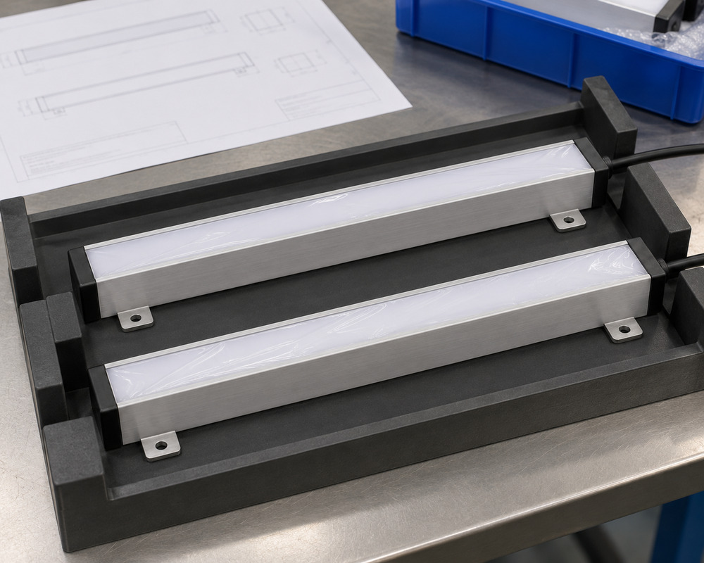
Packaging can protect the diffuser and end connections and identify the assembly for its host. VST supports custom packaging, labels, carton marks, barcodes and brand artwork. Instruction sheets and user manuals depend on the order. Shipment coordination can be discussed; packing quantities, freight costs and transport conditions are agreed for the actual shipment.
Once you choose a mounting approach, consider how the light engine will be serviced and what happens when the host changes. A shared-looking assembly may still have different connections or access requirements. Contact VST about any assembly sequence or service condition your embedded LED lighting project needs to accommodate, so it can be assessed against the proposed design.
Does an embedded LED module include a power supply?+
Not always. Embedded LED modules may be supplied as light engines with an LED board, carrier, diffuser and wiring, or as part of a larger powered assembly. The quotation should identify whether a compatible driver, connector and host wiring are included to avoid installation and sourcing problems.
Can one embedded LED module fit different products?+
Yes, provided the products share compatible mounting dimensions, power requirements, connector interfaces and service access. VST can evaluate a common LED module for multiple equipment or furniture models, with separate samples or revisions where required.
Can the LED module design change after prototyping?+
Yes. VST can review changes to the module dimensions, mounting arrangement, diffuser, wiring or electrical connection after initial sampling. Changes affecting fit or performance may require another prototype and updated assembly documentation before production.
Can embedded LED lighting be replaced independently?+
Yes, when the host product is designed with accessible mounting and electrical connections. A replaceable embedded LED module must be removable through the available service opening without damaging surrounding components. VST can review these requirements during the initial integration design.