Custom LED Module Manufacturer for OEM Product Integration
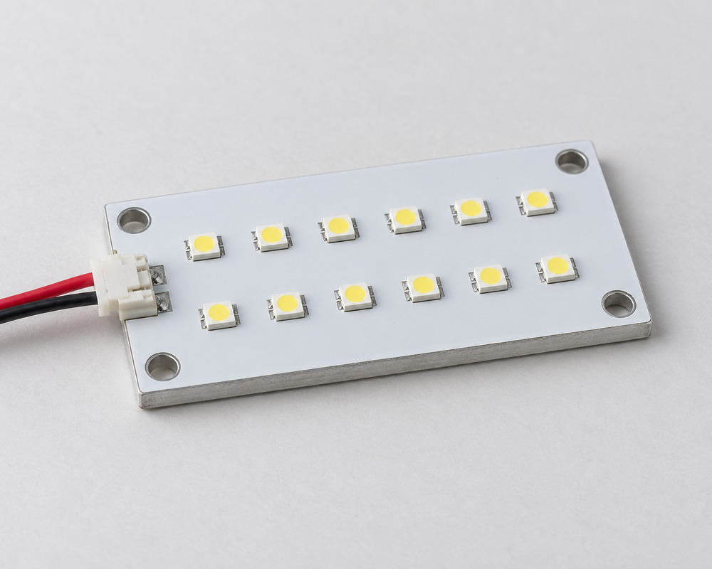
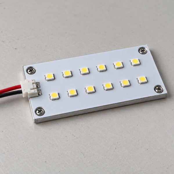
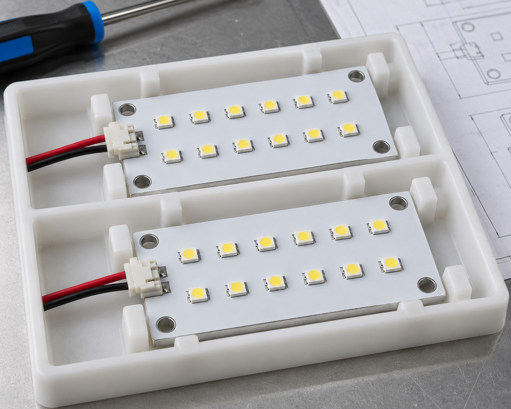
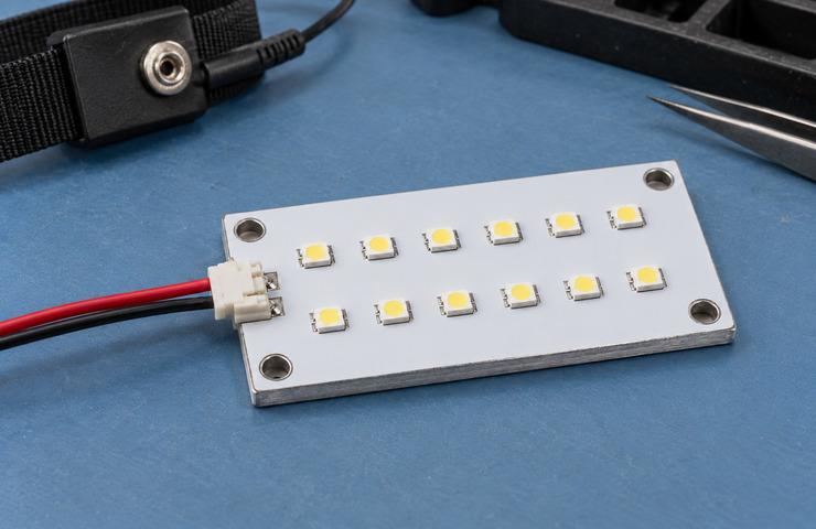
VST Lighting develops and manufactures custom LED modules for lighting brands, equipment manufacturers and OEM product companies. Our LED module customization services cover PCB dimensions, LED layout, optical arrangements, electrical connections and mounting requirements to match your product design.
Whether your project needs an existing LED platform with minor modifications or a completely new light engine, we support engineering review, prototype development, sample testing and repeat production based on agreed specifications.
Custom LED PCB layouts, connectors and optical interfaces developed around your product
Existing platform adaptation or new module development according to project requirements
Sample evaluation and controlled production based on the approved module revision
Share your product drawing, reference sample, lighting requirements or available installation space to begin an engineering review.
Custom LED Modules for Different Product Applications
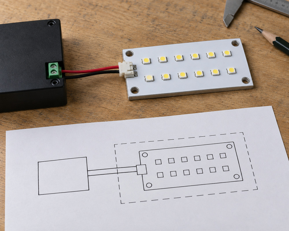
A custom LED module combines the LED light source, circuit board and agreed electrical and mechanical interfaces for integration into another product. Depending on the application, the supplied assembly may also include an optical lens, diffuser, connector or thermal carrier. VST develops OEM LED modules around the lighting function, installation space and components provided by the host product.
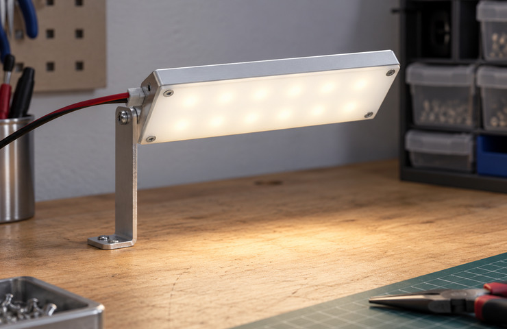
Compact equipment light engine
Operating environment
An indoor enclosure with a restricted source footprint.
Buyer requirement
Deliver task light from a module that follows the available mounting area.
Design constraint
The host establishes the board support and permissible component height.
Design direction
A supported rigid light engine may fit the available area; the remaining luminaire parts need a separate supply definition.
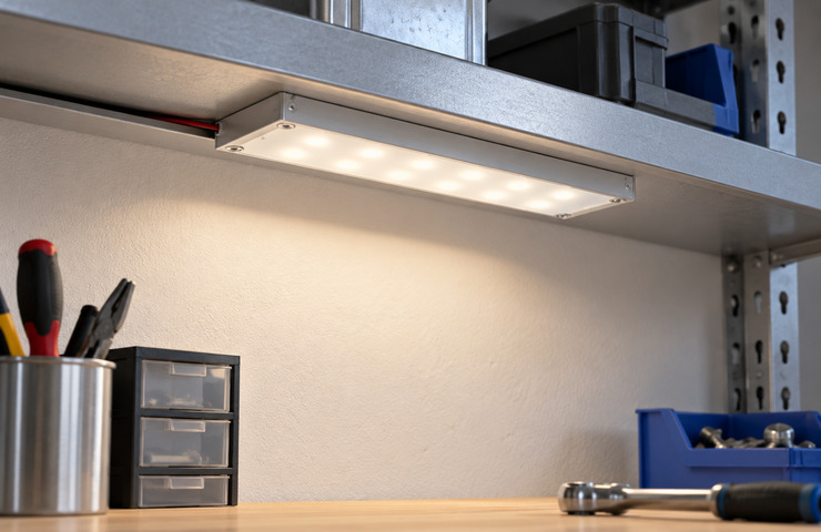
Purpose-built luminaire assembly
Operating environment
A lighting product assembled around a selected optical enclosure.
Buyer requirement
Coordinate LED placement with the housing and secondary optics.
Design constraint
The luminous source must align with the optical seating and thermal contact.
Design direction
Consider a new board layout if a standard footprint compromises optical alignment or thermal contact.
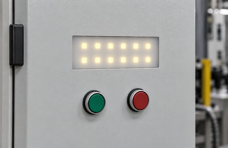
Product-mounted indicator assembly
Operating environment
Indoor equipment with a visible operational indication behind a cover.
Buyer requirement
Provide a clear indication that follows the host control behavior.
Design constraint
The cover and control interface determine how the indication works and appears.
Design direction
Develop the source and connection for the required indication. Establish any addressable protocol separately.
Avoid Common Custom LED Module Sourcing Risks
A board quotation mistaken for a complete module
Purchasing risk: Unpriced optics or thermal parts appear later in the assembly cost.
Confirm: Parts included in the quoted module
VST solution direction: List the board, connection, support and any cover separately from the host parts.
Prototype parts substituted during production planning
Purchasing risk: An apparently minor component change can alter fit or control behavior.
Confirm: Permitted substitutions and critical part identity
VST solution direction: Identify acceptable equivalents and which component changes need an engineering assessment before substitution.
Several competing sample revisions
Purchasing risk: Manufacturing may follow a build that differs from the evaluated sample.
Confirm: Accepted build revision for production
VST solution direction: Use one production definition for the sample, part list and assembly details.
Custom LED Module Design and Manufacturing Options
VST supports OEM LED module customization across PCB design, optical performance, electrical interfaces and assembly requirements. Depending on the application, specifications may include custom PCB dimensions, LED type and layout, input voltage, power requirements, CCT, CRI, luminous flux, mounting holes, connector type and wiring arrangement. Each change is evaluated for compatibility with the finished product and manufacturing process.
Board outline and mounting
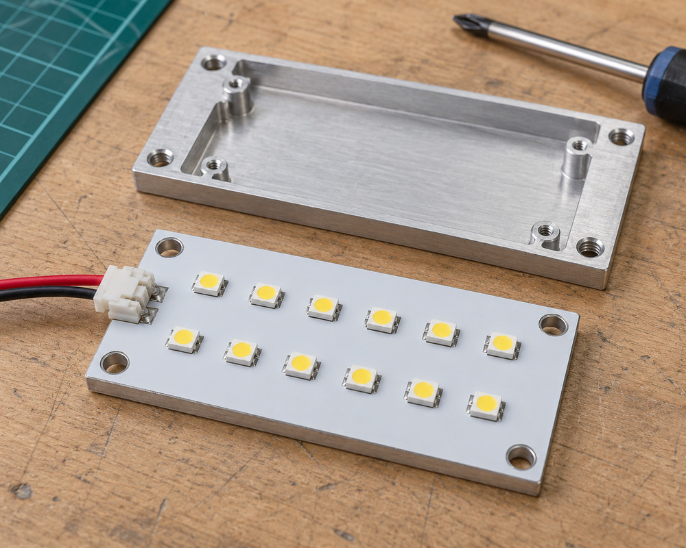
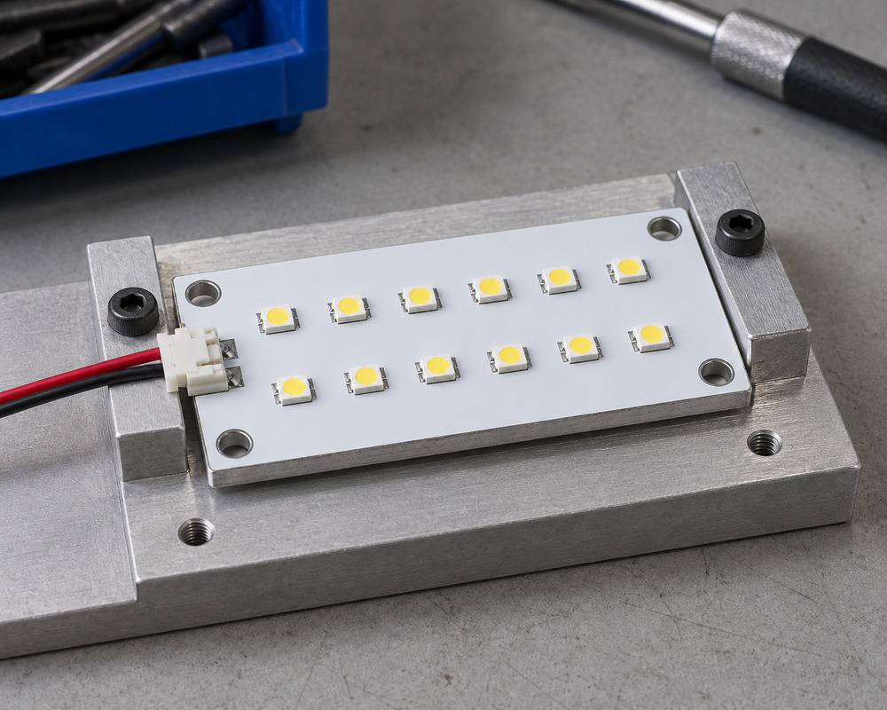
Custom LED PCB dimensions, fixing holes and component positions should match the host product's available mounting area. VST can evaluate different board outlines, LED layouts and support arrangements, including rigid PCB and suitable metal-core PCB constructions where thermal requirements justify them. Changes to board size or shape may affect circuit routing, component clearance, heat dissipation and assembly tooling.
Buyer input: Host locating features and component keep-out zones
Optical arrangement
LED type, placement and optical components determine the module's brightness, light distribution and visual appearance. Depending on project requirements, custom LED modules can be evaluated for luminous flux, correlated color temperature (CCT), color rendering index (CRI), beam distribution and light uniformity. Lens or diffuser selection should be assessed with the intended housing and mounting arrangement rather than the bare LED board alone.
Buyer input: Optical seating surfaces and required illuminated region
Supply and control interface
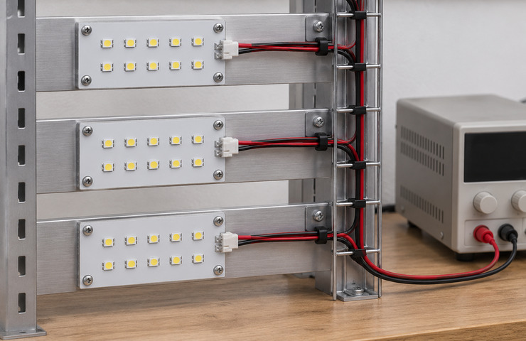
A custom LED module must operate within the specified electrical supply and control system. Depending on the circuit design, this may involve a compatible constant-current driver or constant-voltage power supply. VST reviews voltage, current, power, connector pinout, cable arrangement and applicable dimming or control requirements during development. Electrical and control compatibility must be verified before approving the module for production.
Buyer input: Electrical source limits and required control behavior
Assembly and handling
A custom LED module should be designed for practical installation, handling and repeat assembly. VST reviews mounting access, wiring harness connections, component protection and the need for a supporting carrier or housing. These details can influence assembly time, product thickness, serviceability and packaging requirements, particularly when modules are supplied in bulk for OEM manufacturing.
Buyer input: Host assembly tools and permitted handling surfaces
Standard LED Platform Customization vs. New Module Development
Not every custom LED module requires a new PCB design. When an existing platform meets the main electrical, optical and mechanical requirements, modifying selected connectors or assembly details may reduce development complexity. A new LED PCB layout may be more appropriate when the board shape, LED arrangement or host interface cannot be accommodated by an existing design. VST evaluates both options before confirming tooling, prototype and production requirements.
Decision factor
Suitable platform adaptation
New board and interface
Buyer guidance
Starting constraint
Retains a platform that already fits key requirements
Begins with host geometry and circuit requirements
Use adaptation only when its retained limits suit the application.
Change scope
Selected connection or assembly details may be revised
Board outline and layout can be developed together
Choose a new board when the footprint drives the mismatch.
Production resources
Depends on usable existing assembly methods
May need dedicated fixtures or new part tooling
Evaluate recurring assembly work alongside the initial development effort.
Future flexibility
Later changes remain bounded by the retained platform
Future compatibility follows the new design definition
Avoid assuming either route allows unrestricted later component changes.
From Custom LED Module Design to Production-Ready Assembly
VST supports custom LED module development from initial requirements to an identified production build. The process covers function allocation, PCB and interface layout, prototype assembly, electrical and optical evaluation, and production specification confirmation. Testing and host-product feedback are used to identify design adjustments before the accepted sample revision is released for repeat manufacturing.
01
Allocate module functions
Customer input: Lighting function, available supply, control requirements and the functions that remain outside the module.
VST work: VST separates the proposed light engine, electrical interfaces and surrounding host functions for the quoted assembly.
Stage output: A function and interface scope identifying included parts.
Unsettled electrical or control details are resolved before sample testing.
02
Lay out the sample
Customer input: Board space or outline, locating points, connector position, source placement and component-height limits.
VST work: VST develops the board and support arrangement around the host locating surfaces and intended optical stack.
Stage output: A sample layout showing board features and host interfaces.
An existing sample can support layout discussion without establishing interchangeability.
03
Build and resolve interfaces
Customer input: Choose customer trial feedback or supply a representative host to VST; identify the power, control and thermal interfaces to be checked.
VST work: VST builds the module and measures the agreed component characteristics. We trial the provided host or examine your trial feedback to resolve assembly interfaces.
Stage output: An identified sample revision and the agreed measurement and fit findings.
The trial method and delivered records are specified in the project scope.
04
Transfer the build definition
Customer input: The sample revision to be accepted, resolved changes, required records and component-change requirements.
VST work: VST prepares the component and assembly definition for repeat production from the evaluated revision.
Stage output: A production definition tied to the sample and included parts.
Acceptance of the sample and any remaining conditions is recorded before release.
Custom LED Module Testing and Quality Verification
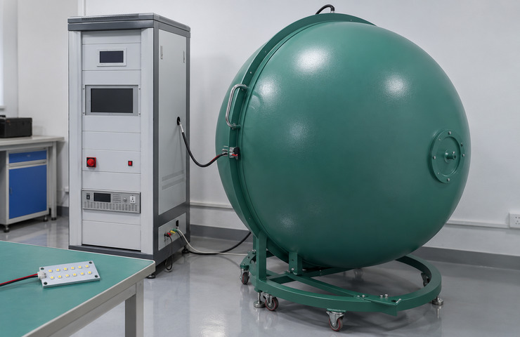
VST evaluates custom LED module samples using agreed optical, electrical, thermal and assembly checks. Depending on the project specification, testing may cover luminous flux, CCT, CRI, voltage, operating current, heat dissipation, connector polarity and powered aging observations. Equipment such as an integrating sphere and goniophotometer supports relevant optical measurements, while dimensional and connection inspections help verify the approved assembly. Results are associated with the tested module revision and operating conditions.
Light output and color
Purpose: Establish the optical characteristics of the chosen light-engine build.
Method: Use an integrating sphere with the sample supported and operated under the recorded supply condition.
Acceptance criteria: The required output and color targets for the defined assembly.
Evidence: A project optical record follows the agreed measurement on the identified module revision; it is not an existing model report.
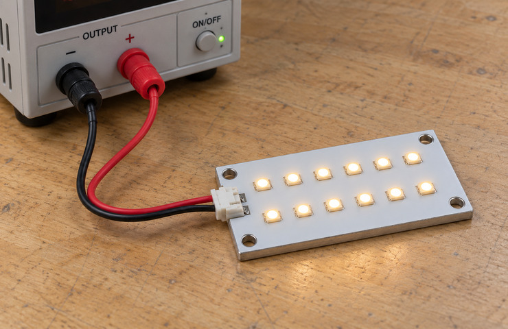
Electrical operating check
Purpose: Detect a mismatch between the module circuit and intended supply.
Method: Connect the sample to a suitable regulated source and measure its operating voltage and current.
Acceptance criteria: Operation within the selected circuit and supply limits.
Evidence: Project electrical readings follow the agreed check and must identify the module revision and applied settings.
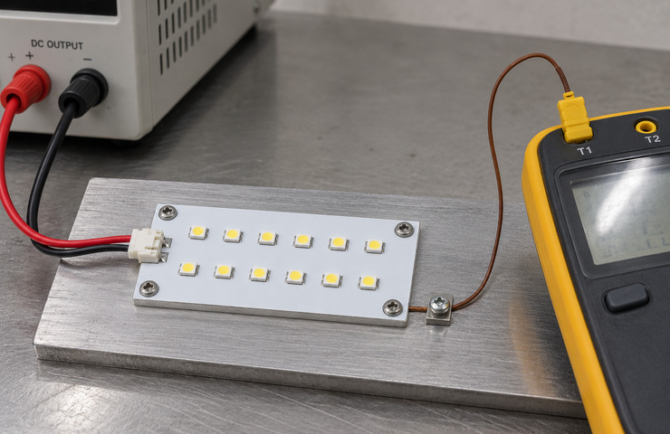
Thermal contact evaluation
Purpose: Determine whether the module support controls heat as intended.
Method: Operate the mounted board and measure selected temperature points on its thermal path.
Acceptance criteria: Relevant component limits and the defined host thermal conditions.
Evidence: If thermal evaluation is agreed, the resulting project record identifies the support contact and sample construction.
Connection and polarity inspection
Purpose: Reduce damage or assembly errors caused by an incorrectly matched harness.
Method: Inspect the mating connector, polarity and lead retention on the representative build.
Acceptance criteria: Correct pin assignment, secure engagement and the agreed harness connection.
Evidence: Project inspection findings follow the agreed connector, polarity and lead-retention check on the selected build.
Powered aging observation
Purpose: Observe operating stability before adopting the sampled build for repeats.
Method: Run the samples under the agreed operating conditions and record changes in function and appearance over the defined test period.
Acceptance criteria: Continued function and acceptable appearance against the module specification.
Evidence: Any agreed operating observation produces a project record of conditions, duration and changes; it is not lifetime proof.
Record the module build and revision
Module interface definition
Project Specific
Project documentation can identify circuit connections, host support and which parts are supplied with the module.
Critical parts and revision record
Project Specific
A development record identifies the build and changes that could affect compatibility in repeat production.
Normal starting MOQs for one model are 500 units with light customization and 1,000 with high customization. Adapting a suitable platform differs from substantial PCB, electrical, optical or structural work. The quotation sets the final quantity for the custom LED module design and the production resources it needs.
Sampling support
VST supports sample development with processing charges. Mold or tooling costs may apply if the build needs new production resources. Eligible sample expenditure can be returned or credited against a subsequent production order. The quotation or order terms specify the amount, eligibility and method; samples are not assumed to be free.
Lead-time factors
Light-customization samples typically take 15-25 working days, followed by 20-30 for bulk production. High-customization samples normally need 30-50 working days, with bulk at 25-35. Scheduling starts when the required technical information and applicable sample, tooling or deposit conditions are complete. Forecast-based reservation of key materials can shorten repeat lead times. These ranges are planning estimates.
Tooling / NRE
A new PCB fixture, optical part or dedicated structural component can incur NRE or tooling costs. Eligible tooling or mold charges may be credited against a later qualifying production payment. The commercial agreement identifies the resource, credit amount and method. A development fee is not automatically refundable in full.
Supply stability
VST coordinates component sources and repeat-production controls for the module. Stable demand may support material preparation from your forecast or reservation of agreed critical parts. Keep replacements and authorized component changes consistent with the build revision, taking account of availability when planning subsequent orders.
Packaging & logistics
Packaging should limit contact with LEDs and connectors while the assembly is handled. VST supports product labels and barcodes, custom cartons and carton marks, and required brand artwork. Instruction sheets and user manuals can follow the quoted module. Shipping coordination uses the actual handling requirements, freight information and packing data for the order.
Clarify the decisions that affect later module changes
Before ordering, establish how the module will be documented and what happens when your product or its components change. A candidate build may need a different division of design work from your existing assembly. Discuss that with VST for your custom LED module, including the interfaces a replacement must preserve and any design rights your project needs to agree.
What should a module quotation distinguish?+
The quotation should separate development charges from recurring product supply. Check which host parts and project work each price includes. A lower unit price does not establish that two proposals cover the same items.
Quoted item
Decision it clarifies
Module unit
Included parts and assembly boundary
Development charges
Project work and dedicated production resources
Excluded host parts
Items required from your own assembly
Can a production module use an equivalent LED later?+
A replacement LED may fit the same pads while changing optical appearance, electrical behavior or assembly interaction. Identify the properties that matter to your host. Decide whether the proposed substitute needs another sample evaluation before it is released for repeat production, even if the package looks similar.
Will one connector make different modules interchangeable?+
Interchangeability requires matching polarity, supply limits and control behavior as well as mechanical fit. Two custom LED modules can use the same connector body and need different electrical settings. Identify the connection assignment and assess compatibility against the complete module specification before treating either one as a replacement.
Does custom development automatically transfer design ownership?+
Design ownership, file delivery, exclusivity and the use of dedicated production resources need a written commercial agreement. A customization order alone does not establish those rights. Specify the documents and permissions your project needs, and record that agreement separately from the module design and unit supply terms.