

A good LED module design starts with the full product system, not with a single LED package or wattage value. Product engineers should define the application environment, electrical architecture, optical target, thermal path, mechanical limits, driver interface, testing plan, and compliance requirements before releasing the module specification.
What an LED Module Design Guide Means
An LED module is an engineered lighting subassembly that usually includes LED packages, a printed circuit board, solder joints, connectors or wires, and sometimes optics, lenses, resistors, ICs, thermal pads, or protective coating. It may be designed for constant-current operation, constant-voltage operation, or a controlled driver circuit inside a larger product.
This guide applies when you need to design or specify an LED module for equipment integration, commercial luminaires, cabinet lights, signage, furniture lighting, industrial devices, display systems, or custom lighting products. Specifically, it helps you decide what to define before quotation, prototyping, testing, and production.
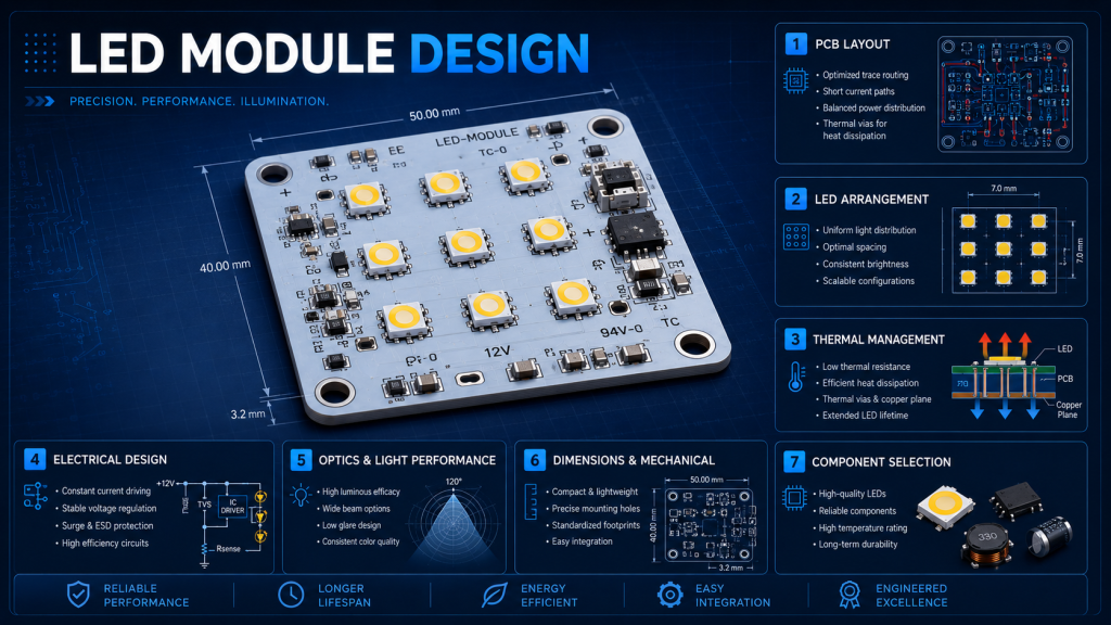
However, LED module design is not only an electrical task. It is a system design task. The LED chip converts electrical energy into light and heat. The PCB carries current and transfers heat. The driver controls power delivery. The housing and mounting surface determine heat dissipation. The optical cover shapes beam angle, glare, and uniformity. Consequently, a weak decision in one area can reduce performance in another.
Why This Matters in Real Projects
In real product development, an incomplete LED module specification often causes late-stage changes. For example, a module may meet wattage requirements but fail thermal testing after it is installed inside a sealed enclosure. In contrast, a module with lower nominal power but better thermal transfer may deliver more stable lumen output and longer service life.
That matters because the final design affects tooling, wiring, assembly time, replacement access, test cost, certification preparation, and warranty risk. A practical LED module design guide helps engineers reduce these risks before the project reaches mass production.
Key Terms Product Engineers Should Define First
- Before selecting components, define the technical terms that drive the module design. This avoids confusion between the lighting target, the electrical input, and the physical installation conditions.
- Luminous flux is the total visible light output, usually measured in lumens. Luminous efficacy means lumens per watt. It helps compare efficiency, but it should be evaluated at the expected operating temperature, not only at ideal test conditions.
- CCT, or correlated color temperature, describes the color appearance of white light, such as 2700K, 3000K, 4000K, or 6500K. CRI, or color rendering index, indicates how accurately colors appear under the light source. SDCM describes color consistency between LED modules. A lower SDCM value usually means tighter color consistency.
- Forward voltage is the voltage drop across the LED at a specified current. Drive current directly affects brightness, heat, efficiency, and lifetime. Junction temperature is the LED semiconductor temperature. It is one of the most important reliability factors.
- IP rating describes protection against dust and water. IK rating describes impact resistance. These ratings matter when modules are used in outdoor, wet, dusty, public, or industrial environments.
Core Technical Principles Behind LED Module Design
Electrical Design Starts with Current Control
LEDs are current-driven devices. A small change in current can change light output and heat generation. Therefore, product engineers should not treat LEDs like simple resistive loads. The circuit must control current safely across temperature changes, LED bin variation, and driver tolerance.
Constant-current designs are common when stable output and LED protection are priorities. Constant-voltage designs, such as 12V or 24V modules, are common when modular wiring, cut lengths, or simple system integration are needed. However, constant-voltage modules still need proper current regulation through resistors or onboard components.
Thermal Design Protects Light Output and Lifetime
Every LED module converts part of its input power into heat. If heat cannot move from the LED junction through the solder pad, PCB, thermal interface, housing, and ambient air, the junction temperature rises. Consequently, lumen output drops, color may shift, and component stress increases.
Thermal planning should include LED package selection, PCB material, copper thickness, copper area, via design, thermal pad contact, adhesive or screw mounting, enclosure ventilation, and ambient temperature. Aluminum PCB is often used for higher thermal load. FR4 may be suitable for lower power designs when thermal performance is verified.
Optical Design Controls User Experience
Optical design includes LED spacing, beam angle, lens choice, diffuser material, cover distance, surface reflectance, and module placement. For example, a narrow beam can increase intensity but may create hotspots. A diffuser can improve uniformity but reduce transmitted lumens. In contrast, a clear lens may improve efficiency but increase glare.

Product engineers should define whether the design goal is high efficiency, soft uniform light, high center intensity, narrow beam control, or color quality. The LED module cannot optimize all goals at once without trade-offs.
Mechanical Design Affects Assembly and Maintenance
Mechanical details often decide whether a module is easy to install. Mounting hole location, connector direction, cable exit angle, screw clearance, board thickness, thermal pad position, and tolerance stack-up can add or reduce assembly time.
In equipment integration, a module that looks correct on a drawing may still be difficult to install if the technician cannot access screws or connectors. Therefore, engineers should review the module inside the actual product enclosure before approving final layout.
Step-by-Step Guide for Designing an LED Module
The design process should move from application conditions to performance targets, then to component selection, layout, testing, and production control. This sequence reduces redesign because it connects technical decisions to real project constraints.
Step 1: Define the Application Environment
Start with where the module will operate. A module inside a ventilated display cabinet has different requirements from a module inside a sealed industrial enclosure. Specifically, confirm ambient temperature, humidity, dust exposure, cleaning method, vibration, UV exposure, and maintenance access.
If the module is used outdoors or in wet areas, check the required IP rating and connector sealing. If the product may face impact, check whether IK rating or mechanical reinforcement is needed. Do not select these ratings after the layout is finished. They influence enclosure design, cable entry, coating, and testing.
Step 2: Set the Optical Target
Define how much light the module must deliver after optical losses. If a diffuser, lens, cover, reflector, or silicone layer is used, the LED output must compensate for transmission loss. However, increasing wattage to recover lost lumens also increases heat. This is why optical and thermal design should be reviewed together.
For retail, display, furniture, and architectural applications, CCT, CRI, and SDCM can be as important as lumen output. A high-lumen module with poor color consistency can still fail visual inspection when installed in rows or groups.
Step 3: Select the Driver Strategy
Choose the driver method based on system requirements. Constant-current drivers are often suitable for stable output and controlled LED loading. Constant-voltage drivers can simplify modular installation but require proper onboard current control. Dimming requirements should be confirmed early because PWM, 0-10V, DALI, TRIAC, and other methods behave differently.
Driver compatibility also affects flicker, minimum load, dimming range, inrush current, EMC performance, and wiring layout. Consequently, the driver should be tested with the actual LED module, not only reviewed by datasheet values.
Step 4: Build the Thermal Design
Thermal design should be validated under realistic operating conditions. Measure board temperature at key locations and estimate or verify LED junction temperature according to the LED manufacturer’s guidance. If the module is installed inside a closed housing, test it inside that housing because free-air testing can be misleading.
Step 5: Release a Controlled Specification
A released module specification should include input voltage, current, wattage, lumen output, CCT, CRI, SDCM, beam angle, PCB dimensions, mounting method, connector type, cable length, polarity, IP rating, operating temperature, dimming method, testing requirements, packaging, labeling, and compliance expectations.
Technical Factors to Check Before Prototype Approval
Prototype approval should not depend only on whether the module lights up. A professional review checks performance, reliability, manufacturability, safety, and repeatability. This matters because many LED module failures come from borderline design decisions that only appear after aging, heat buildup, or field installation.
Electrical and Thermal Checks
Start by verifying input power, including voltage, current, wattage, polarity, and tolerance under rated operating conditions. This reduces the risk of driver overload or inconsistent brightness.
Thermal performance should also be reviewed carefully. Measure board temperature, heat sink contact, and ambient effects. Use thermocouples, a thermal camera, or enclosed-product testing where relevant.
Optical, Dimming, and Mechanical Checks
Photometric output should be tested by reviewing lumens, beam angle, CCT, CRI, and color consistency. Use an integrating sphere, goniophotometer, or color test method when required.
Dimming behavior must be tested with the specified driver and controller. This helps identify flicker, dropout, buzzing, or unstable low-end dimming.
Mechanical fit should be confirmed inside the actual housing. Review hole position, board size, cable routing, and connector clearance before approving the prototype.
Environmental and Compliance Checks
Environmental resistance may also need testing. Moisture, dust, temperature, vibration, and coating adhesion can affect corrosion risk, water ingress, and electrical stability.
Compliance documentation should be prepared early. Material records, safety review, EMC planning, RoHS status, and the certification path can affect project schedule and approval risk.
How LED Module Design Affects Product Selection and Specification
Product selection becomes more accurate when the specification describes the module as part of a complete lighting system. For example, “24V, 12W LED module” is not enough for engineering procurement. A stronger specification would include rated current, luminous flux, CCT, CRI, SDCM, PCB material, module size, connector type, dimming method, operating temperature, and test requirements.
In contrast, an incomplete specification often leads to quotations that are difficult to compare. One supplier may quote a higher-efficiency LED package. Another may quote a lower-cost LED with looser color binning. Another may exclude photometric testing, special cable length, conformal coating, or labeling. Consequently, the lowest price may not represent the lowest project cost.
Specification Example
A practical module specification may read: 24V constant-voltage LED module, 10W nominal power, 4000K, CRI 90 minimum, 3-step SDCM target, aluminum PCB, 120-degree beam angle with diffuser, 300 mm cable, indoor dry location, operating ambient temperature from -20°C to 45°C, compatible with specified PWM dimming driver, with photometric and electrical test data required.
This type of specification gives engineering, purchasing, and manufacturing teams the same reference point. It also reduces disputes during prototype approval and incoming quality inspection.
How Design Choices Affect Installation and Project Execution
Installation efficiency depends on the physical and electrical details designed into the module. A module with clear polarity marking, accessible mounting holes, suitable cable length, and stable connector placement is easier to assemble and service. However, a module with poor routing, tight screw access, or fragile connectors can slow production even if its optical performance is acceptable.
Voltage drop is another common execution issue. Long cable runs, small wire gauge, high current, and multiple modules in parallel can reduce voltage at the far end of the circuit. This may cause uneven brightness. Specifically, 24V systems often perform better than 12V systems in longer runs because current is lower for the same wattage, but the final choice depends on driver availability, safety requirements, and product architecture.
Maintenance access should also be designed early. If an LED module is bonded permanently into a sealed housing, replacement may require full product disassembly. In contrast, screw-mounted modules with serviceable connectors can reduce field maintenance time. The best choice depends on product cost, IP rating, warranty policy, and expected service model.
Cost, Reliability, Safety, and Compliance Considerations
Cost control in LED module design should focus on total project cost, not only component cost. Lower-cost LEDs, thinner copper, minimal testing, or simplified connectors may reduce the first quotation. However, they can increase thermal risk, color variation, installation labor, scrap rate, or maintenance cost.
Reliability Planning
Reliability depends on electrical derating, thermal margin, solder quality, moisture protection, driver stability, and production consistency. For this reason, engineers should review LED datasheets, LM-80 data where available, and TM-21 projections when lifetime claims are important.
Testing and Certification
LM-79 photometric testing may be relevant for complete luminaires or finished products. EMC testing, CE marking, UL or ETL evaluation, RoHS material compliance, IEC safety requirements, and local electrical code may apply depending on the product and target market.
Finished-Product Approval
Do not assume that a component-level rating automatically covers the finished product. A certified driver or LED package does not mean the full module or luminaire is certified. The final construction, wiring, enclosure, thermal condition, insulation, creepage, clearance, labeling, and installation method can all affect approval.
Common Misunderstandings in LED Module Design
Misunderstanding 1: Higher Wattage Always Means Better Performance
Higher wattage can increase lumen output, but it also increases heat. If the thermal path is weak, the module may deliver lower stable performance over time.
Misunderstanding 2: Datasheet Lumens Equal Installed Lumens
Installed output can be lower because of diffuser loss, lens loss, high temperature, driver loss, and enclosure absorption.
Misunderstanding 3: Any Driver with the Same Voltage Will Work
Driver compatibility depends on load range, current capacity, dimming method, flicker behavior, protection mode, EMC performance, and wiring layout.
Misunderstanding 4: IP Protection Can Be Added at the End
Water and dust protection affect enclosure design, cable entry, coating, connector type, adhesive, gasket design, and testing.
Misunderstanding 5: Color Difference Is Only a Procurement Issue
LED binning, SDCM requirement, thermal condition, optical materials, and production batch control all affect visible color consistency.
What This Means in Practice
In practice, product engineers should treat LED module design as a controlled system specification. Define the target result first, then work backward into electrical, thermal, optical, mechanical, and compliance requirements.
Compact equipment lights often face heat buildup inside small enclosures, while retail display modules typically require careful control of color consistency and glare. Industrial modules must address dust, vibration, temperature variation, and service access, whereas furniture or cabinet modules need strong hotspot control, clean cable routing, and low-profile installation.
The right module is not always the highest-output module. It is the module that fits the product environment, driver system, mounting structure, visual target, compliance path, and maintenance plan with enough engineering margin.
Pro Tip | Field Experience
Always test the LED module inside the actual housing, with the real driver, cable length, diffuser, and mounting method. Bench testing in open air can hide thermal buildup, voltage drop, flicker, connector stress, and optical loss. A short enclosed-system test before final quotation often prevents expensive changes after tooling, certification review, or production pilot runs.
Final Design Review Checklist
Before approving the module for quotation or pilot production, review the following points with engineering, procurement, quality, and manufacturing teams. This helps align performance expectations with production reality.
- Review target lumen output after optics, diffuser, lens, cover, and temperature effects.
- Verify voltage, current, wattage, circuit type, driver compatibility, dimming method, and wiring layout.
- Check PCB material, copper thickness, thermal pad position, mounting pressure, and heat dissipation path.
- Define CCT, CRI, SDCM, LED binning, color tolerance, and batch control requirements.
- Inspect module dimensions, hole position, connector type, cable length, polarity marking, and service access.
- Validate IP rating, IK rating, coating, sealing, operating temperature, and environmental exposure where relevant.
- List required tests, such as electrical, thermal, photometric, aging, EMC, environmental, and production inspection.
- Document compliance expectations, labeling, packing, sample approval process, and change-control rules.
You can contact a technical team to confirm project details when the module involves custom dimensions, special optical targets, strict color consistency, sealed installation, high operating temperature, or market-specific compliance requirements.