SC1212 · close cabinet task
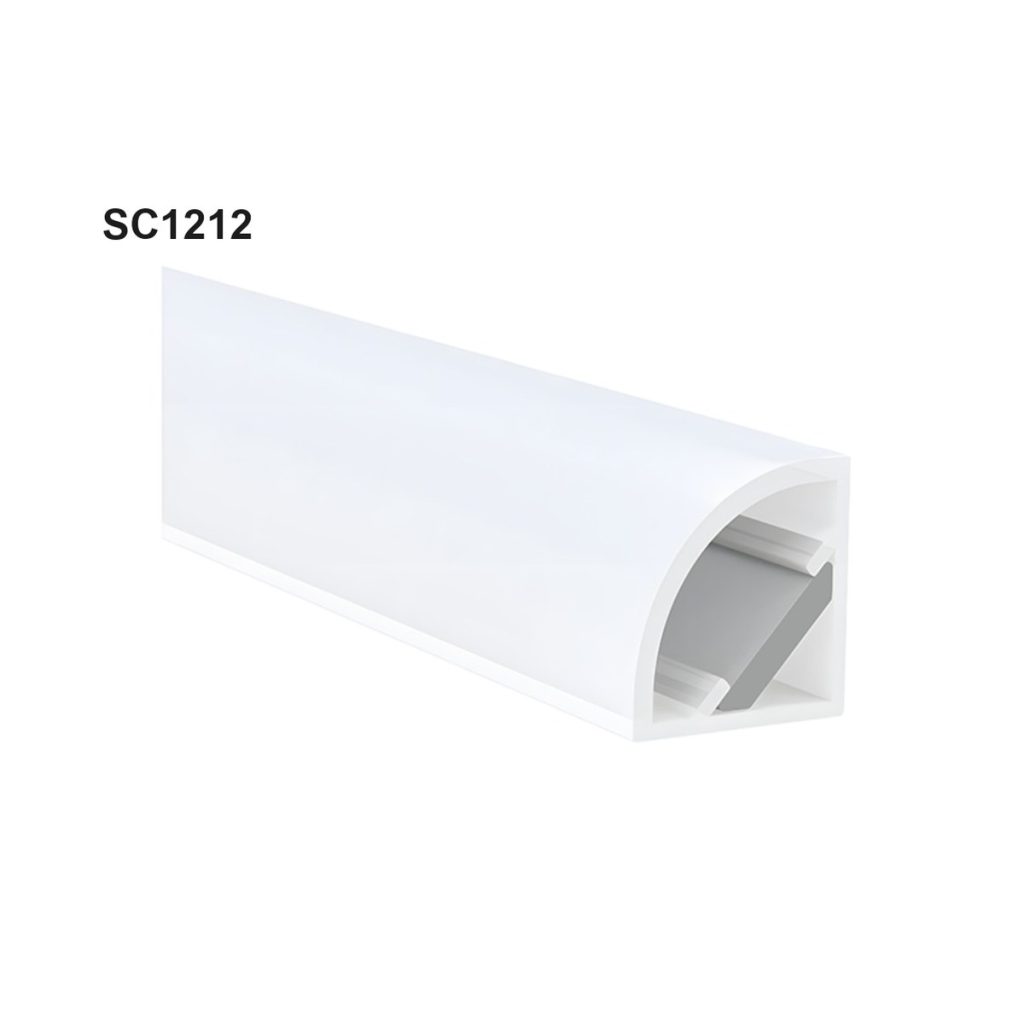
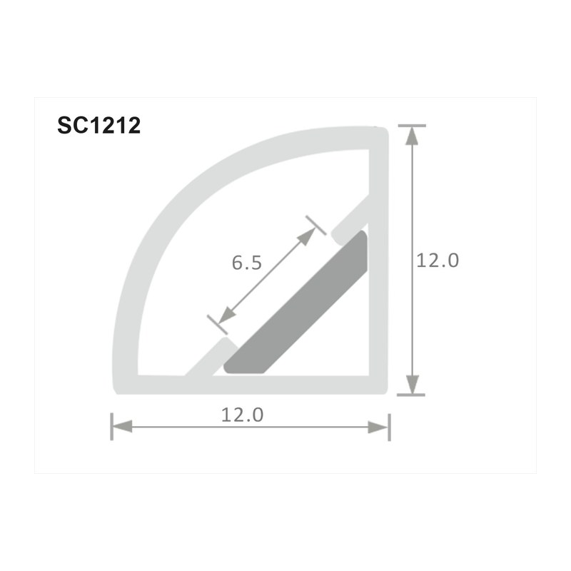
A compact 12 × 12 mm body for tight junctions where the strip is no wider than the published 6 mm limit.
View Product Directed linear light

Placement first
Mark the counter, wall or shelf that should receive the light; the profile angle is useful only when the position supports that task.
Check the normal eye line from standing and seated positions, especially when a clear cover or reflective surface is involved.
A rear-corner cabinet detail and a front-edge detail can need different strip output even with the same aluminum channel.

Optical selection
The published SC series includes compact equal-sided sections and the asymmetric SC2016, so mounting clearance and aim can be compared without inventing a new body.
A short assembly viewed at the intended shelf depth can reveal glare or shadows that an unlit section drawing cannot show.
VST can discuss tape width, density and cover appearance as a combination; a broader channel does not automatically give the right task-light result.
Recording the setback from the target surface helps later fixture or cabinet batches reproduce the approved light direction.
Angled emission
Same SC family
Design checks
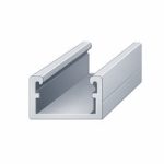
The strip sits on an angled face so its light can be redirected away from the two surfaces meeting at the corner.

An opal or milky cover can soften the visible line, while actual dot visibility still depends on LED density and profile depth.

Measuring the distance to the target surface turns a visual preference into a placement detail that can be repeated.

A channel end should land where the fixing and electrical lead can be concealed without interrupting the visible line.
Assembly components
Metal section
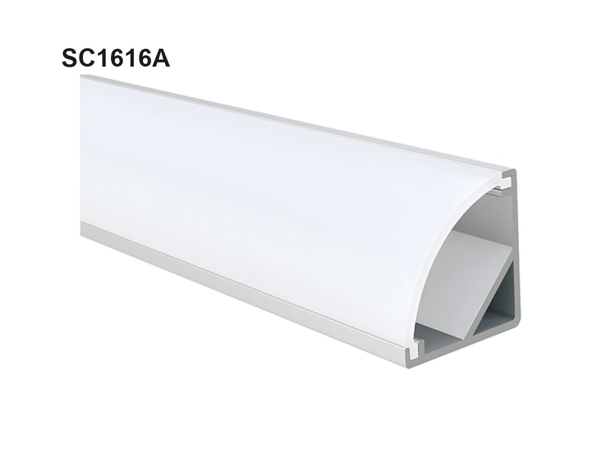
Visible face
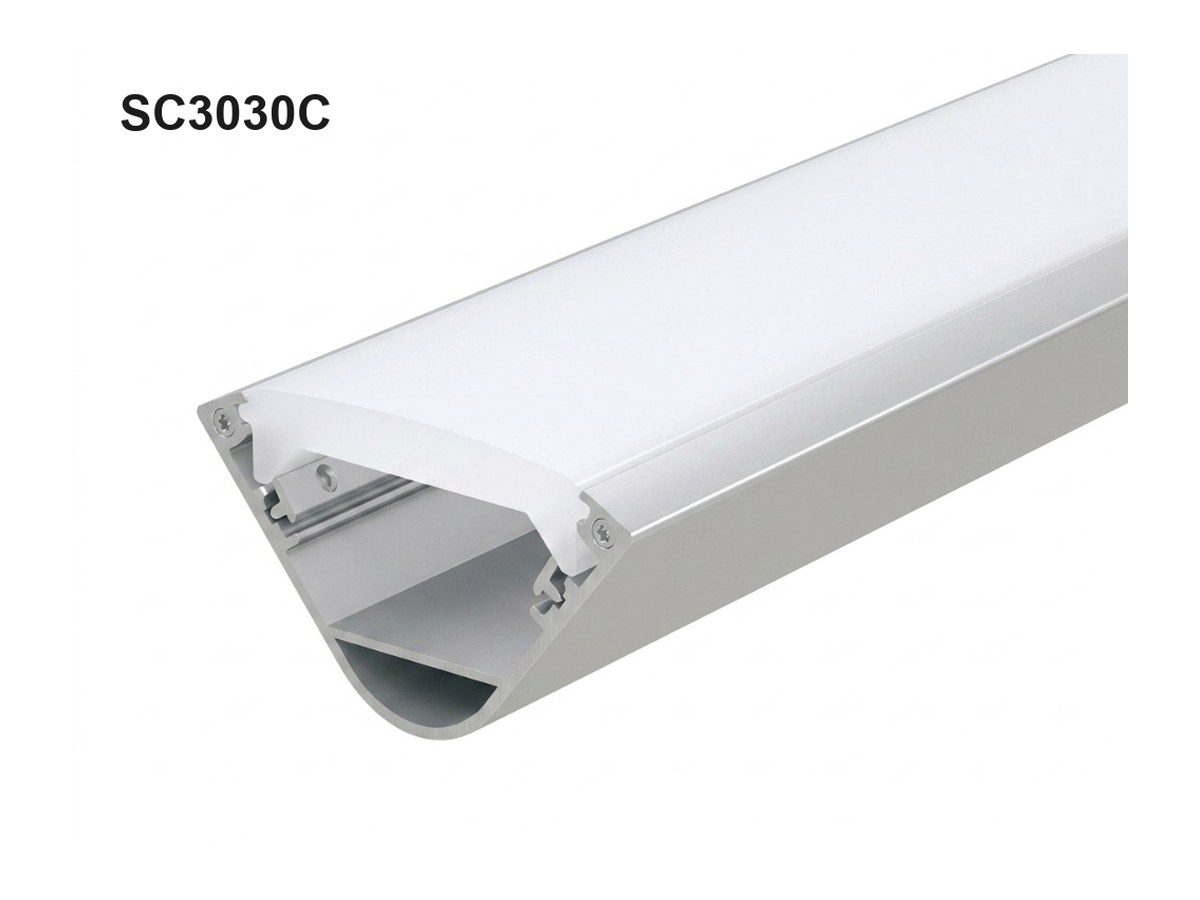
Site interface
Company context
The company video introduces VST’s LED lighting and component work. For an angled channel order, specify the model code, diffuser and sample placement.
The customer video describes cooperation with VST. Judge this channel’s light direction using a powered sample at your chosen setback.
Placement examples
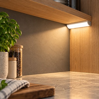
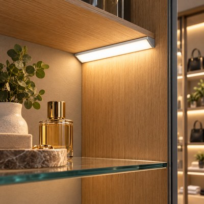
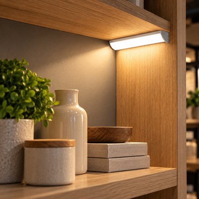
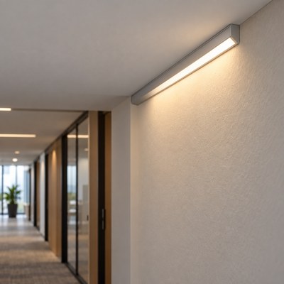
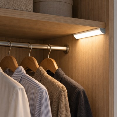
Test the aim
Published data
| Model | Published section and strip space |
|---|---|
| SC1212 | W 12 × H 12mm; Up to 6mm strip |
| SC1616A | W 16 × H 16mm; Up to 10mm strip |
| SC1919D | W 19 × H 19mm; Up to 11mm strip |
| SC1919J | W 19 × H 19mm; Up to 12mm strip |
| SC2016 | W 20 × H 16mm; Up to 12mm strip |
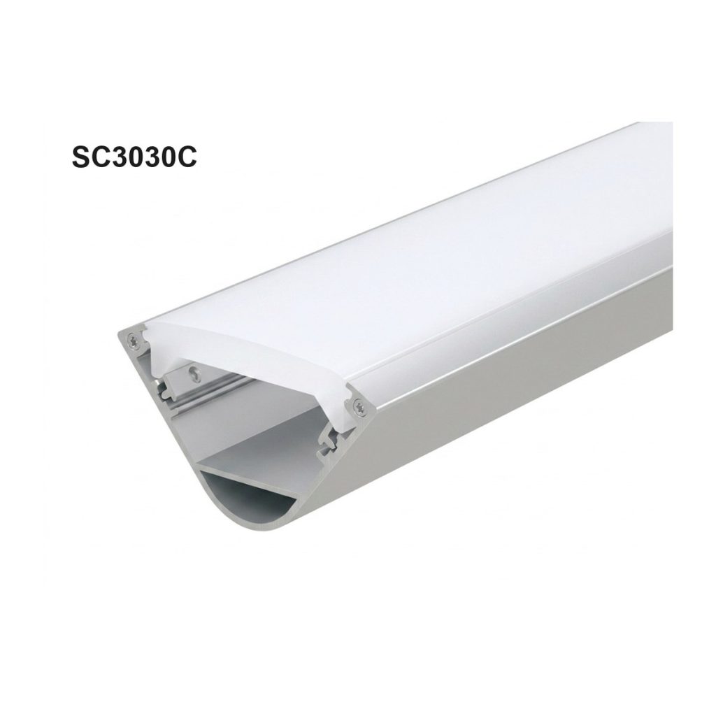
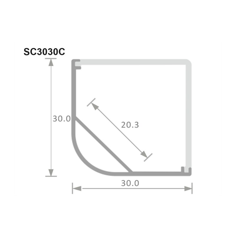
| SC3030C | W 30*H 30mm; Up to 20mm strip |
Project feedback
Supply questions
Angled-channel questions
| Position | Main check |
|---|---|
| Rear upper corner | Reach across the worktop |
| Front underside edge | Direct glare at the eye line |
| Side panel junction | Shadows from stored objects |