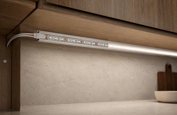
VST develops custom LED strip lights for the actual profile, viewed surface and power route. As a custom LED strip lights manufacturer, we specify the PCB, LED pitch, cut interval and lead together. Send a profile photo and approximate run length to compare an existing platform with a new board.
Cut positions and lead entry matched to assembly
SMD or COB appearance chosen for the real viewing distance
Long-run voltage and thermal path considered early
Share the mounting profile, intended run and available supply; the first enquiry does not need a complete drawing.
Where the Strip Must Fit
A strip must fit its channel, manage heat at the mounting surface and keep its light level along the full run. Choose the host profile and power unit with the strip even when they are ordered separately.
Cabinet light channel
Operating environment
Furniture shelf with close viewing
Buyer requirement
A clean light line under the shelf
Design constraint
Profile depth and cable passage are narrow
Design direction
VST matches board width and source spacing to the finished channel
Display shelf wash
Operating environment
Retail fixture with merchandise below
Buyer requirement
Even illumination at the display plane
Design constraint
Long row can dim at its far end
Design direction
As a custom LED strip lights supplier, VST plans feed spacing and lead route for the real run
Equipment enclosure
Operating environment
Metal equipment cabinet
Buyer requirement
Local visibility for service tasks
Design constraint
Existing supply, grounding and thermal surfaces vary
Design direction
The strip is retained on a suitable carrier with protected wiring
Constraints That Change the Strip Specification
The desired cut length falls between available cut marks.
Purchasing risk: An improvised cut can sever the circuit or leave an unusable section.
Confirm: Required segment length
VST solution direction: Choose a board/cut interval that fits the actual assembly.
Only the input end of a long run is checked.
Purchasing risk: Voltage drop may make the far end visibly dimmer.
Confirm: Longest run and feed location
VST solution direction: Evaluate the selected strip at the full planned length.
A bare strip is specified without a heat path.
Purchasing risk: LED and adhesive temperatures may rise on the host surface.
Confirm: Carrier material and exposure
VST solution direction: Pair the board with a suitable profile or substrate and installation method.
Connector choice is left until the product is assembled.
Purchasing risk: A thick plug may not fit inside the channel or access opening.
Confirm: Mating half and cable route
VST solution direction: Define the connection envelope with the strip build.
At a custom LED strip lights factory, a platform adaptation may change LED density, cut length or lead format within an existing board family. A new PCB, optical cover or special protection route is developed when the existing platform cannot meet fit or appearance.
Board and cut interval
PCB width, copper layout, LED pitch and cut marks can be selected for the required segment length. A shorter cut interval may change circuit architecture and manufacturing cost.
Buyer input: Profile width and shortest segment
Light appearance
SMD and COB constructions serve different viewing distances. Diffusion, CCT, color rendering and LED density are chosen with the actual channel depth and task surface.
Buyer input: Viewing distance and target surface
Electrical layout
Voltage, feed positions, wire size and control method can be set for the longest run. The selected scheme must match the driver and dimming device.
Buyer input: Supply and longest powered run
Protection and joining
Adhesive, carrier, silicone cover, lead entry and connector can follow the installation exposure. A protection method should not be claimed as a rated seal without supporting design and tests.
SMD has individual LED packages on the bare board; COB presents a continuous emitting line. The profile depth, diffuser and viewing distance determine which construction looks right in your product. Compare samples in the same channel.
Discrete SMD StripContinuous COB Strip
Decision factor
Discrete SMD Strip
Continuous COB Strip
Buyer guidance
Source appearance
Individual packages are visible on the bare board
A continuous phosphor line covers the emitting area
Judge both in the intended diffuser and at viewing distance.
Board structure
Packages and cut pads follow the chosen PCB
Dense emitters sit beneath a continuous conversion layer
Do not assume identical repair or cut behavior.
Profile depth
May need more mixing depth to hide source points
Can provide a smoother line in a shallow section
Choose the profile and strip together.
Connection
Lead or connector lands on defined pads
Cut and lead preparation follows its PCB design
Keep the wired sample with the final PCB and connector specification.
Application choice
Useful when package layout and board access matter
Useful when close-up continuity is the main visual goal
As a custom LED strip lights manufacturer, VST maps the host channel to a PCB width, cut pattern and feed positions. A connected full-length sample checks the electrical run before the construction is released for production.
01
Channel and run map
VST work: Relate the strip width and cut marks to the profile and installation route.
Stage output: A segment and feed-position plan.
02
Electrical sample
VST work: Build the board, lead and intended power connection.
Stage output: A connected sample ready for host evaluation.
03
End and diffuser fit
VST work: Seat the strip and connector into the actual carrier and end.
Stage output: A closed section proving the assembly sequence.
04
Production reference
VST work: Record PCB population, cut layout, adhesive or cover and lead variant.
Stage output: A versioned bill and assembly instruction.
As a custom LED strip lights supplier, VST checks the selected strip at the length and mounting condition you intend to use. Electrical, optical, thermal and connection checks are specified around that run.
Sphere optical setup
Purpose: Characterize light and color of the selected short sample.
Method: Mount the entire unlit sample inside an open integrating sphere, route a protected feed, then close the door to measure.
Acceptance criteria: Evaluate measured light and color against the target for this strip build.
Evidence: A light and color measurement sheet follows an agreed test on the selected strip.
Temperature path
Purpose: Locate heat buildup on the board and aluminum carrier.
Method: Run the assembled strip on its intended support and log representative points after stabilization.
Acceptance criteria: Observed temperatures stay within the selected components and host limits.
Evidence: Board and carrier temperature points can be logged for the assembled strip.
Full-run electrical check
Purpose: Detect excessive drop between input and far end.
Method: Operate the longest planned strip with its intended supply and compare voltage at both ends.
Acceptance criteria: Voltage and appearance match the agreed full-run requirement.
Evidence: Near- and far-end voltage observations can be listed for the planned run length.
Cut and connection fit
Purpose: Check the prepared lead, connector and carrier.
Method: Inspect the cut pads and retention on a short assembled section with appropriate fixtures.
Acceptance criteria: The cut and connection remain secure in the released assembly.
Evidence: The accepted cut, joint and carrier details can be added to the strip build record.
Strip Definition and Test Files
The file set follows the PCB and installation version actually selected.
PCB and cut map
Project Specific
Shows populated board, cut marks and feed arrangement.
Connection drawing
Project Specific
Identifies lead, polarity and mating interface.
Agreed test record
Project Specific
Records only the measurements actually performed on the released run.
A light change to an existing strip platform normally starts at 500 units for one model. A new PCB or major electrical construction generally uses a 1,000-unit starting point for that model. Cut length and connector variants are identified in the quote.
Sampling support
VST supports connected samples for profile fit, full-run operation and appearance checks. Processing charges apply; a new board or dedicated tool may create additional cost. The order terms can provide a refund or credit of qualifying sample costs on a subsequent batch.
Lead-time factors
Light customization normally allows 15–25 working days for samples and 20–30 working days for production. Deep customization normally allows 30–50 working days for samples and 25–35 working days for production. Timing begins after the circuit, run and applicable fees or deposit are settled.
Tooling / NRE
A new PCB, silicone cover or joining tool may involve NRE or mold cost. An eligible charge can be credited toward a later order under an agreed qualifying quantity, amount and written credit method.
Supply stability
For repeat strip orders, the cut map, PCB population and color target remain on the released specification. VST may reserve agreed PCB materials or LEDs against a stable forecast, shortening preparation for the next run. Finished reels still follow the order.
Packaging & logistics
Reels or cut sections need bend control, appropriate static protection and clearly identified leads. The order may use customized reel labels, section bags, manuals, carton marks, installation sheets, brand artwork and barcodes.
A short strip sample may look right while the longest installed run loses brightness or needs a feed in an awkward place. Check the cut interval, profile fit and supply boundary before the first order. The quote should distinguish the bare strip from the profile, diffuser and driver, and identify the PCB and connector version you would need for a replacement.
Can the strip be cut to any length?+
Only at valid cut positions for the chosen circuit. A different interval may require another platform or PCB layout. The segment plan states the actual usable lengths.
Does the quotation include the profile and driver?+
The quote separates the light engine from agreed accessories.
Part
Specify before order
Strip
PCB, LEDs and cut points
Profile
Carrier and diffuser supplied or separate
Power
Driver, control and feed scheme
How is a longer run checked before bulk production?+
Use the longest intended section with the planned feed and profile. Compare the voltage and visible line at its near and far ends after operation stabilizes.
Can an existing connector be retained?+
Yes when the mating geometry, current rating and assembly space suit the chosen strip. Supplying the mating half avoids a connector that fits electrically but not physically.
How are replacement strips identified later?+
The released version ties PCB population, cut interval, color target, protection and lead to a part reference. A replacement should match that reference and the host driver.